How to Wire a DIN Electrical Connector for a Solenoid Valve
DIN electrical connectors are commonly used in solenoid valves across industrial automation, fluid control, and pneumatic systems. Wiring these connectors correctly ensures optimal valve performance, safety, and longevity. This guide walks you through the exact steps for wiring a DIN connector, including tools, diagrams, and expert tips.
What is a DIN Electrical Connector?
A DIN connector is a standardised interface used to connect electrical components. In solenoid valves, DIN 43650 (also known as Form A, B, or C) is the most commonly used standard. These connectors offer a secure, waterproof seal and are ideal for harsh industrial environments.
DIN 43650Form A: Standard for most solenoid valves square
Industrial Form B: Smaller footprint rectangular
DIN 43650 Form C: Compact applications
Tools and Materials Needed
DIN connector (Form A/B/C depending on your valve)
Screwdriver (flat-head or Phillips)
Wire stripper
Multi-meter (optional but recommended)
Electrical wires (sized according to your solenoid valve specs)
Step-by-Step Wiring Instructions
Step 1: Disconnect Power
Always turn off power to the valve before beginning any wiring work to avoid electric shock.
Step 2: Open the DIN Connector
Unscrew and remove the top cap of the connector to expose the terminals.
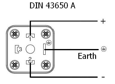
Step 3: Identify the Terminals
Most DIN connectors have 3 terminals:
1 (Positive)
2 (Negative or Neutral)
⏚ (Ground/Earth)
Step 4: Strip and Insert Wires
Strip around 5–6 mm of insulation from the wire ends. Insert each wire into the appropriate terminal.
Step 5: Tighten Screws
Secure each wire using the terminal screws. Ensure wires are not loose or exposed.
Step 6: Reassemble the Connector
Reattach the DIN cap and tighten the screw securely.
Step 7: Test the Connection
Restore power and test the solenoid valve using a multimeter or system controller to verify functionality.
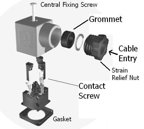
Also ensure correct fitting of the gasket between the connector and the coil with correct or adequate torque.
Typical Torque Settings for DIN connectors are:
Strain relief nut: 1.8 N/m +/- 10%
Central fixing screw: 0.4 N/m +/- 10%
Contact Screw: 0.2 N/m +/- 10%
It is also important as correct sizing and fitting not only protects the electrical system but also everything and everyone around the connector. Keeping the circuits safe, dry and helping to keep the cable securely fixed in place.
Troubleshooting Tips
Double-check wire polarity and grounding
Ensure no short circuits or frayed wires
If the solenoid doesn’t activate, test voltage at the connector terminals
Orientation of the connector is also important
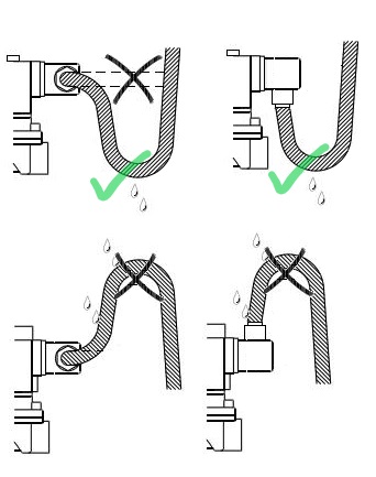
Make sure the cable conduit entry is facing down and that the electrical cable has sufficient slack in it so that it drops under the connector and back vertically up and into the conduit entry of the plug.
This will help prevent water ingress gravitating into the connector through the conduit entry, keeping it safe, so any moisture droplets will gravitate away from the conduit entry point.
Helpful Hint: Avoid cable entry pointing upwards, fasten locking screw securely and fill connector with silicone sealant in moist environments.
Related Resources
Solenoid Valve Fault Diagnosis