Calculate Flow Rate from Pressure a Practical Guide
To work out flow rate from pressure, you're essentially measuring the pressure differential – the difference in pressure between two points – and then plugging that value into a formula, often based on Bernoulli's equation. This pressure drop is the force that gets the fluid moving in the first place. By measuring it, you can figure out the fluid's velocity and, from there, its flow rate.
Understanding the Link Between Pressure and Flow
Before you can measure anything, you've got to understand what you're measuring. At its heart, fluid only moves because of a difference in pressure, a concept we call pressure differential. It’s the invisible force pushing water through a pipe or air through a duct. If there’s no pressure difference between two points, a fluid will simply stay put.
This fundamental relationship is the cornerstone of any attempt to calculate flow rate from pressure. It’s not just theory; it’s a practical principle that technicians and engineers across the UK’s water and industrial sectors rely on every single day.
The Role of Pressure Drop
When a fluid travels through a pipe, it loses a bit of energy. This is down to friction against the pipe walls and the turbulence created by things like bends, valves, and other fittings. This loss of energy shows up as a drop in pressure along the pipe's length.
Crucially, this pressure drop is directly proportional to the flow rate. If you crank up the flow, the pressure drop increases right along with it. This is incredibly useful because it lets us figure out the flow by measuring something much simpler: pressure. By fitting pressure gauges at two points in a system, we can capture this pressure drop and use it as a key piece of our puzzle.
Key Takeaway: A higher flow rate creates more friction and turbulence, resulting in a larger, more measurable pressure drop. This direct link is what makes pressure-based flow calculation possible.
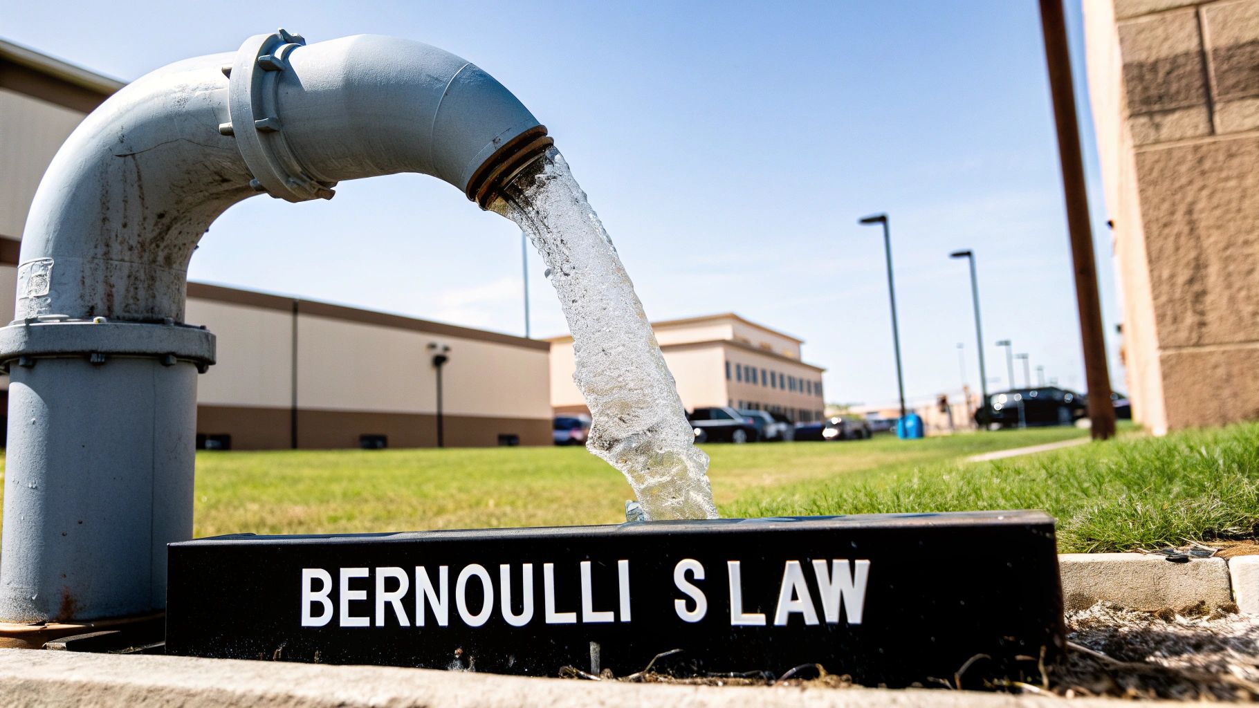
Bernoulli's Principle in Action
The science behind all this is beautifully explained by Bernoulli's principle, a foundational concept in fluid dynamics. In simple terms, it states that for a fluid in motion, when its speed goes up, its pressure goes down.
Picture a constriction in a pipe, like a Venturi meter or an orifice plate.
- As the fluid gets squeezed through this narrower section, its velocity has to increase to keep the same volume moving through.
- According to Bernoulli, this jump in velocity causes a corresponding drop in pressure.
By measuring the pressure just before the constriction and right at its narrowest point, you can find the pressure differential. Pop that value into the right formula, and you'll get a surprisingly accurate flow rate. Understanding this principle makes sense of the tools and equations you'll be using for your calculations.
This isn't just for industrial pipes, either. The principle is applied on a massive scale for environmental monitoring. For instance, the National River Flow Archive (NRFA) is the UK's main hub for river flow data, which is vital for everything from flood forecasting to managing water resources. Data from over 1,400 gauging stations is used to calculate daily mean flow in cubic metres per second (m³/s), often using these very same pressure-based measurement techniques. You can find out more about how this data is gathered across the UK at the CEH's National River Flow Archive.
Choosing the Right Formula for Your Calculation
Once you've got the core principles down, the real work begins: picking the right mathematical tool for the job. To get an accurate flow rate from a pressure reading, you need a formula that truly matches your specific fluid, pipe setup, and the way you're measuring. It's a bit like a carpenter choosing the right saw for a specific cut – an engineer needs the right equation for the flow scenario at hand.
The choice isn't random. It’s dictated by the conditions you're facing. Are you working with a clean, predictable fluid in a brand-new, smooth pipe? Or is it a more complex situation, like water flowing through an old, corroded industrial system? Each scenario demands a specific approach to get results you can trust.
Bernoulli's Equation as a Foundation
At its heart, most flow calculation is built on the back of Bernoulli's equation. It's the theoretical foundation connecting pressure, velocity, and elevation in a fluid. While it's perfect for ideal, frictionless fluids, the real world is rarely that simple. In practice, friction always causes some energy loss.
That’s why we almost always use modified versions of Bernoulli’s principle for on-the-job calculations. These practical formulas build in correction factors to account for the energy losses that happen in any real system, making them far more useful in the field.
The Orifice Plate Formula for Differential Pressure
One of the most tried-and-tested methods is to create a deliberate restriction in the pipe using an orifice plate. This is just a thin plate with a precisely machined hole that makes the fluid speed up as it passes through, causing a pressure drop that we can easily measure.
The formula here is a direct descendant of Bernoulli's equation, but with a critical addition: the discharge coefficient (Cd).
- What it is: The discharge coefficient is a dimensionless number that corrects for real-world messiness. It accounts for the small energy losses and flow contraction that an ideal equation like Bernoulli's simply ignores.
- Why it matters: Without it, your flow rate calculation could be wildly inaccurate. The value of Cd is typically found through experiments and depends on the orifice plate design and the pipe's Reynolds number. For many standard plates, a value of around 0.61 is a good starting point.
This method is a favourite in industrial settings because it's robust, reliable, and well-understood. It gives you a solid way to calculate flow rate from a simple pressure differential.
The Darcy-Weisbach Equation for Friction Loss
But what if you don't have an orifice plate or Venturi meter installed? You can still figure out the flow rate by measuring the natural pressure drop that happens over a straight section of pipe due to friction. For this, the industry gold standard is the Darcy-Weisbach equation.
This formula is specifically built to calculate head loss (which is just another way of saying pressure loss) from friction inside a pipe. By rearranging the equation, you can work backwards to solve for velocity and, from there, the flow rate.
Expert Tip: The real power of the Darcy-Weisbach equation is its use of the friction factor (f). This single variable cleverly accounts for both the pipe's internal roughness and the flow's turbulence (via the Reynolds number). This makes it incredibly versatile for anything from smooth new plastic pipes to older, corroded cast iron systems.
To get started, you'll need to know a few key details about your system. This table breaks down the variables you'll encounter in these common formulas.
Key Variables in Flow Rate Formulas
| Variable Symbol | Description | Common SI Unit |
|---|---|---|
| Q | Volumetric Flow Rate | m³/s (cubic metres per second) |
| ΔP | Pressure Drop / Differential | Pa (Pascals) or bar |
| ρ (rho) | Fluid Density | kg/m³ (kilograms per cubic metre) |
| D | Internal Pipe Diameter | m (metres) |
| f | Darcy Friction Factor | Dimensionless |
| L | Length of the Pipe | m (metres) |
Ultimately, choosing between these formulas comes down to your setup. If an orifice plate is installed, use its dedicated formula. If you're simply analysing flow in a straight run of pipe, Darcy-Weisbach is your best bet.
Getting Your Instruments Set Up for Accurate Measurements
You can have the best formula in the world, but it’s completely useless if your input data is garbage. When you're trying to figure out flow rate from pressure, the quality of your measurements is everything. Your calculations are only as good as the readings you pull from your instruments, so getting the setup right isn't just a suggestion—it's the foundation of the whole process.
This is where we move from theory to the workshop floor. The aim is to capture a clean, true static pressure differential, without the ‘noise’ and errors that can throw your results way off.
Selecting and Installing Your Instruments
Your workhorses for this kind of job will usually be differential pressure (DP) transmitters or, for more straightforward setups, simple manometers. A DP transmitter is ideal for automated systems because it gives you a continuous electronic signal that’s proportional to the pressure difference. A manometer, on the other hand, gives a direct visual reading, which is brilliant for quick spot-checks and diagnostics.
To accurately determine flow rate from pressure, you absolutely need the right tools. A reliable pressure gauge, for example, is non-negotiable for getting precise readings. When you're installing it, double-check that the device's pressure rating is right for your system to prevent damage or outright failure.
Good instrument selection also includes the bits and pieces around your main sensor. For instance, if you need to constantly adjust pressure in your system, you need to know how your valves work. You can learn more about how specialised valves operate in our guide to pressure reducing valves. This kind of knowledge helps you see the bigger picture and make sure your entire measurement and control loop is configured properly. https://www.solenoid-valve.world/pressure-reducing-valves
The Critical Role of Pressure Taps
The placement of your pressure taps—those small holes you drill into the pipe—is probably the most critical part of this whole setup. Getting this wrong is a common mistake, and a costly one at that, leading to skewed readings that send you down a rabbit hole.
Field Technician's Tip: Always, and I mean always, place your pressure taps well away from anything that causes turbulence. That means bends, valves, pumps, and pipe reducers. A solid rule of thumb is to allow for at least 10 pipe diameters of straight, clear pipe upstream and 5 pipe diameters downstream from where you’re measuring.
This straight run gives the flow a chance to stabilise. It ensures you’re measuring a representative static pressure, not the chaotic fluctuations you get in a turbulent flow.
Common (But Avoidable) Setup Mistakes
Anyone who's spent time in the field has seen a few things go wrong. A few common errors pop up again and again. If you can dodge these, you’ll save yourself a lot of frustration and rework.
- Incorrect Tap Orientation: This is a classic. For liquids, your taps should go on the side of the pipe (think the 3 o'clock or 9 o'clock position). This stops sediment from clogging the taps at the bottom and prevents trapped air from forming bubbles at the top. For gases, put the taps on the top of the pipe so any condensed moisture can drain away.
- Forgetting to Purge Impulse Lines: Those little tubes connecting your pressure taps to the transmitter are called impulse lines. Before you take any readings, you must purge them of any trapped air (for liquid systems) or condensate (for gas systems). A tiny air bubble can create a massive pressure offset and make your measurement completely worthless.
- Mismatched Tap Diameters: Make sure your upstream and downstream pressure taps are drilled to the exact same diameter and are deburred cleanly. Even a slight difference can create a mini-flow disturbance right where you’re trying to measure.
Real-World Examples of Flow Rate Calculations
Theory is one thing, but getting your hands dirty with real-world problems is where you really start to build confidence. Let's walk through a couple of practical scenarios you might actually face in the UK, putting these principles into action to see how you calculate flow rate from pressure in a real-world setting.
We'll kick things off with a classic industrial setup before jumping over to an environmental application. I'll break down the process for each, from getting your initial readings to arriving at a solid, usable answer.
This infographic breaks the core process down into three logical steps.
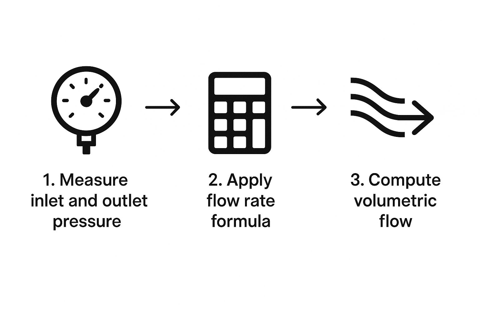
As you can see, the path from a pressure reading to a final flow rate is pretty clear: measure the pressure drop, pick the right formula, and then run the numbers to get your volumetric flow.
Industrial Water Flow Using an Orifice Plate
Picture this: you're a process engineer at a manufacturing plant in Birmingham. Your task is to verify the flow rate of cooling water running through a 150 mm internal diameter steel pipe. The good news is the system already has a standard orifice plate fitted, and a differential pressure (DP) transmitter is giving you the pressure drop reading.
Here's what you know:
- Pressure Drop (ΔP): The DP transmitter is showing 50 kilopascals (kPa), which translates to 50,000 Pascals.
- Fluid: It's water, sitting at about 20°C. That gives it a density (ρ) of roughly 998 kg/m³.
- Orifice Details: You're working with a standard orifice with a discharge coefficient (Cd) of 0.61. The orifice bore itself has a diameter of 75 mm (or 0.075 m).
- Pipe Diameter (D): The internal diameter of the pipe is 150 mm (0.15 m).
First up, you need to calculate the cross-sectional area of both the pipe (A) and the orifice (a). You'll use the trusty area formula, A = π * (diameter/2)².
- Pipe Area (A): 0.0177 m²
- Orifice Area (a): 0.0044 m²
Now, it's time to plug these values into the orifice plate flow equation. This is the go-to formula for this exact scenario, letting you calculate the flow rate (Q) directly from the pressure drop and the geometry you have. Punching in the numbers gives you a reliable flow rate – absolutely critical for keeping the process under control.
Key Takeaway: When you have a system with a built-in flow element like an orifice plate, the calculation is refreshingly straightforward. Your main job is to trust your pressure readings and make sure you're using the correct discharge coefficient for your specific device.
Environmental Flow in a Drainage Culvert
Let's shift gears to an environmental job, like monitoring a drainage culvert after some heavy rain in the Pennines. In this situation, you won't find a neat, pre-installed orifice plate. Instead, you'll be estimating flow using pressure head measurements, a common technique in hydrology.
Your objective is to estimate the flow rate in a 1-metre diameter concrete culvert. You've measured the water depth—the pressure head—at the culvert's inlet, and it's 0.75 metres.
For this kind of open-channel flow, Manning's equation is the perfect tool. It directly links the flow rate to the channel's shape, its roughness (in this case, concrete), and the slope of the water.
This is where having good regional data becomes invaluable. In the UK, statistical analysis of river flow trends reveals significant regional differences in peak flow rates, all derived from pressure data at gauging stations. For instance, research based on the UK National Flood Dataset has highlighted rising flood magnitudes, especially in northern and western Britain, driven by climatic shifts. You can dive deeper into these national-scale trend assessments and see how they influence flow calculations.
These two examples really show how versatile pressure can be for figuring out flow. It doesn't matter if you're in a controlled industrial pipe or an unpredictable natural channel—the fundamental principle holds true.
Avoiding Common Pitfalls to Improve Accuracy

Even when you've got the right formulas and a perfectly set-up instrument, small oversights can throw your results way off. To really get a handle on calculating flow rate from pressure, you need to be aware of the subtle things that can skew your data. This is the kind of know-how that takes your work from a rough guess to a reliable measurement.
One of the most common mistakes I see is treating fluid properties like they're set in stone. Fluid density and viscosity aren't static; they shift with temperature. For example, if you use the standard density for water at 20°C but your process water is actually running at 60°C, you're baking a noticeable error right into your final calculation. Always use values that match your real-world operating conditions.
Ignoring Pipe Roughness in Calculations
Another frequent slip-up is forgetting about the condition of the pipe itself, especially when you're using the Darcy-Weisbach equation. The internal roughness of a pipe creates friction, which has a direct effect on pressure drop. A brand-new, smooth plastic pipe is going to have a much lower friction factor than a 10-year-old steel pipe with a bit of corrosion or scale build-up.
Expert Tip: Never assume a pipe is perfectly smooth. Unless you're dealing with a new installation, it's best to use a standard roughness value for the pipe's material and age as a starting point. Ignoring this can lead to underestimating the pressure loss and, as a result, getting an inaccurate flow rate.
Misinterpreting Your Flow Element Data
If you're using a device like an orifice plate or Venturi meter, the discharge coefficient (Cd) is absolutely critical. This isn't a one-size-fits-all number; it’s specific to the flow element's design and the conditions it's operating under (characterised by the Reynolds number). Using a generic Cd value like 0.61 might be fine for a quick check, but for high-accuracy work, you really need to consult the manufacturer's specific calibration data.
Other components in your system can also mess with your pressure readings. It’s vital to understand what every valve is doing. For instance, knowing how certain components handle overpressure is crucial for both system safety and getting a stable measurement. Our guide on https://www.solenoid-valve.world/pressure-relief-valves goes into more detail on how these essential safety devices work within a fluid system.
Finally, you have to be realistic about when a simplified calculation is good enough. For a quick operational check, an estimate might be perfectly fine. But for critical processes, fiscal metering, or safety systems, a more detailed analysis that accounts for all these variables is non-negotiable. Knowing the difference is what separates the pros from the amateurs.
Frequently Asked Questions About Flow Rate Calculation
Even with all the right formulas in front of you, practical questions always come up when you're trying to figure out flow rate from pressure. Let's tackle some of the most common queries we hear from engineers and technicians out in the field.
Can I Use the Same Formula for Gases and Liquids?
In short, no. While the underlying principles of fluid dynamics are the same, you can't just plug a gas into a formula designed for a liquid. The big difference is compressibility.
Liquids are, for all practical purposes, incompressible. This means their density stays constant, which really simplifies the calculation.
Gases are a different story. They are highly compressible, so their density shifts with any change in pressure. To get a reliable flow rate, you have to account for this by bringing an expansion factor (Y) into your equation and applying the relevant gas laws. Trying to use a liquid formula for a gas without these key adjustments will throw your results way off.
What Is the Most Common Mistake When Measuring Pressure Differential?
From what I’ve seen, one of the most frequent—and easily avoidable—mistakes is the incorrect placement of pressure taps. It seems like a small detail, but getting it wrong can completely ruin your data.
If you place your taps too close to any kind of system disturbance, like a pump, a bend in the pipe, or a valve, your sensor will pick up all the turbulence. This gives you chaotic, unstable pressure readings instead of the clean, steady differential you need for an accurate calculation.
Crucial Tip: To get a stable, trustworthy measurement, always stick to the industry rule of thumb: leave at least 10 pipe diameters of straight, clear pipe run upstream of your measurement point, and 5 pipe diameters downstream. This gives the flow profile a chance to settle and normalise.
How Important Is the Pipe's Internal Roughness?
It's extremely important, especially if your calculations rely on the Darcy-Weisbach equation. The pipe's internal roughness is a critical variable that directly feeds into the friction factor in your formula.
Simply assuming a pipe is perfectly smooth is a classic mistake, particularly in older systems where corrosion or scale buildup is likely. A higher roughness value leads to a higher friction factor, which directly changes the calculated pressure drop for any given flow rate.
For results you can actually trust, you need to use a realistic roughness value (ε) that matches your pipe's specific material and condition. This, combined with quality instrumentation, is the key to precision. Our selection of pressure transducers can help ensure your setup is capturing the most accurate data possible.