Form A IO Link Connector Temp, Cycle + Diagnostic Monitoring
£75.60
Description
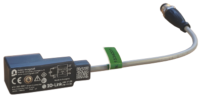
Nass Magnet Smart Connector (Form A) 611-202-0507
**Smart Connector (Design A) – IO-Link Enabled Valve Control Module**
**Advanced Solenoid Driver with Timer Modes, Diagnostics & RGB LED**
**Features & Benefits**
**Built-in Timer Functionality (Standard Mode)**
* Operates **without IO-Link** using **predefined timers**
* Set **Switch-On and Switch-Off times** to automate valve actuation
* Delivers full voltage during pull-in phase (up to 2000 ms), then switches to **PWM mode** for power savings
* Ideal for systems without continuous PLC/IO-Link control
**IO-Link Communication for Smart Automation**
* IO-Link V1.1 interface enables **real-time process monitoring** and **remote configuration**
* Supports **Class A IO-Link ports** with 2.8 ms cycle time (COM2 speed)
* Compact 3-pin **M12 connector** for plug-and-play setup
**Live Diagnostics for Predictive Maintenance**
* Measures and reports:
* **Supply voltage**
* **Output current & resistance**
* **Power consumption**
* **Internal temperature**
* **Valve switching time**
* Dual **switch cycle counters** with warning thresholds help track lifespan of connected devices
**Multicolour RGB LED with “Find Me” Mode**
* Assign custom LED colours for ON, OFF, and ALERT states
* “Find Me” mode cycles LED through all 7 colours for easy identification during maintenance
**Dual Operating Modes**
1. **IO-Link Mode**: Full-featured control and diagnostics via master
2. **Standard Mode**: Operates as a self-contained smart driver with timer/PWM presets
**Built-in Data Storage**
* Saves all configuration settings internally
* Automatically transfers settings to replacement units — **saving setup time and reducing downtime**
**Technical Specifications**
**Electrical**
* **Rated Voltage:** 24 VDC
* **Operating Range:** 10–30 VDC
* **Max Output Current:** 500 mA (depending on master)
* **Self-Consumption:** <10 mA
**Interface**
* **Connector:** M12, 3-pin A-coded
* **IO-Link Revision:** V1.1
* **Master Port Type:** Class A
* **Cycle Time:** 2.8 ms
* **Transfer Rate:** COM2 (38.4 kbit/s)
* **Process Data:** 1 byte IN / 1 byte OUT
* **SIO Mode:** Not supported
**Environmental**
* **Temperature Range:** -25°C to +80°C
* **Protection Class:** IP65 / IP67
**Timer & PWM Settings**
* **Switch-On Timer:** Up to 2000 ms
* **PWM Duty Cycle:** Adjustable (default 50%)
* **Switch-Off Timer:** Supported in Standard Mode
* **PWM Mode Active in:** Both IO-Link and offline modes
**LED Colours**
* Off, Blue, Green, Cyan, Red, Magenta, Yellow, White
Technical Specification
Brand: Nass Magnet GmbH
Model: 611-202-0507
Width: 27.30 mm
Height: 24.00 mm
Depth: 62.00 mm
Weight: 0.50 kg
Valve / Product Type: Timed control
Body Material: Nylon
Voltage: 24vDC
Seals: NBR
Approval: ATEX,WRAS,IP etc: IP65
Options required: Position Feedback Closed, Position Feedback Open+Closed, Position indication Visual
Spares (Coils, Connectors, Seals): DIN connector Form A