Your Guide to the Pressure Relief Valve
A pressure relief valve is one of the most critical safety devices you'll find in any pressurised system. Think of it as the essential, automatic safety whistle on a pressure cooker, but engineered for demanding industrial, commercial, and even residential applications. It's designed to automatically protect a system from a catastrophic failure.
Why Pressure Relief Valves Are So Important
Picture the immense and unseen energy stored within industrial pipelines, boilers, or chemical reactors. If operating conditions go wrong—perhaps due to a blockage, equipment malfunction, or an external heat source—this pressure can build to devastating levels in seconds. A pressure relief valve (PRV) acts as the silent guardian, the final line of defence against this dangerous overpressure.
It's vital to realise that a PRV is not a process control device used for regulating normal system pressure. Instead, it’s a purely mechanical, automatic safety component that sits inactive during normal operation. Its one and only job is to spring into action when pressure exceeds a pre-determined safe limit, venting the excess fluid to prevent disaster.
The Last Line of Defence
The importance of this single component simply cannot be overstated. A failure to relieve excess pressure can lead to severe consequences, making the PRV a non-negotiable part of any pressurised system. Without a functioning valve, a system is vulnerable to:
- Catastrophic Equipment Failure: Overpressure can rupture tanks, vessels, and pipes, leading to incredibly expensive damage and extended operational downtime.
- Environmental Incidents: The uncontrolled release of hazardous chemicals or pollutants can cause significant environmental harm and hefty regulatory penalties.
- Risk to Human Life: Most importantly, a system failure can result in explosions or the release of high-pressure fluids, posing a direct and lethal threat to any personnel nearby.
To get a sense of their practical importance, just consider the crucial role PRVs play in preventing overpressure in everyday systems like automotive air conditioning systems.
A Cornerstone of Industrial Safety
The market for these devices really highlights their critical role. The global pressure relief valve market was valued at over $5 billion in 2023, with significant demand in the UK driven by stringent safety regulations from bodies like the Health and Safety Executive (HSE). This growth underscores the essential function these valves serve in protecting critical infrastructure across sectors like power generation and chemical processing. You can explore a full report on this market trend from DataHorizzon Research.
In essence, a pressure relief valve is an insurance policy made of metal. It sits dormant, waiting for a worst-case scenario, and its reliable function is the key to preventing a manageable issue from becoming a catastrophe.
By automatically and reliably managing overpressure events, the humble PRV is a cornerstone of modern industrial safety. For those looking to specify or purchase these components, our guide on pressure relief valves offers a detailed overview of the options available.
How a Pressure Relief Valve Actually Works
To really get what a pressure relief valve does, you have to look past its simple shell and see the elegant physics going on inside. At its heart, a standard spring-loaded PRV is locked in a constant mechanical tug-of-war between two opposing forces. It’s a beautifully simple system with a single job: to automatically keep pressure in check, no human or electronic intervention needed.
Think of it like a heavily reinforced, spring-loaded trapdoor. The spring is calibrated with incredible precision to hold that door shut against a normal, expected amount of force. This downward spring force is what we call the valve's set pressure. Pushing up against this door is the internal pressure from whatever is in your system—be it gas, steam, or liquid.
During normal operation, the system pressure isn't strong enough to beat the spring's force, so the valve stays sealed up tight. Nothing happens; the valve just sits there, waiting. This state of balance is where the valve will spend 99% of its life.
The Critical Operational Sequence
The real action starts when things go wrong. An upset in the system, like a blocked outlet or an external fire, can cause the internal fluid pressure to surge. As this upward force builds, it starts to seriously challenge the downward push of the spring.
The whole cycle can be broken down into three clear phases. This diagram shows exactly how a pressure relief valve goes from being sealed to fully active and back again.
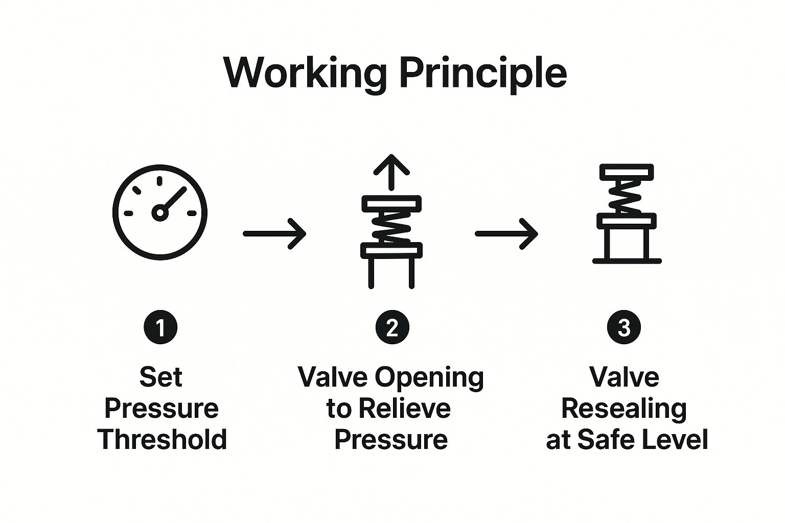
As the infographic shows, this is a completely automated process. It’s driven entirely by system pressure, ensuring the valve seals itself again once the danger has passed.
From Cracking to Reseating
The sequence kicks off the very moment system pressure matches the spring’s resistance.
Cracking Pressure: This is the tipping point where the system pressure is just strong enough to start lifting the valve disc off its seat. The valve "cracks" open, letting a small amount of fluid escape. It's the first hint that the valve is doing its job.
Full Lift: If the pressure keeps climbing, it shoves the disc further open until it hits its maximum travel, known as full lift. At this point, the valve is dumping fluid at its maximum rated capacity. It's rapidly venting the dangerous excess pressure to get the system back under control—the valve's emergency mode in full swing.
Reseating Pressure (Blowdown): As the valve vents, system pressure starts to drop. Once it falls to a safe, predetermined level—the reseating pressure—the spring's force wins the battle again. The spring slams the disc back down onto its seat, creating a tight seal and getting the system back to business as usual.
The difference between the pressure at which the valve opens (set pressure) and closes (reseating pressure) is called blowdown. This gap is absolutely vital; it stops the valve from rapidly flapping open and closed (a problem known as "chattering") when the system pressure is hovering right around the set point.
This entire sequence happens on its own, often in just a few seconds. It’s a purely mechanical dance, which makes the pressure relief valve an incredibly reliable safety device, protecting expensive equipment, the environment, and people from the immense forces at play in pressurised systems.
Exploring Common Pressure Relief Valve Types
While every pressure relief valve shares the same core mission—keeping a system safe—they are far from being one-size-fits-all. The engineering behind them varies enormously to handle different applications, pressures, and fluid types. Getting these details right is the difference between genuine, reliable protection and a false sense of security.
The world of PRVs is really split into two main families: direct-acting (or spring-loaded) valves and their more sophisticated cousins, pilot-operated relief valves. Each works on a completely different principle, bringing its own set of strengths and weaknesses to the table.
The Workhorse: Direct Spring-Loaded Valves
The most familiar and straightforward design is the direct-acting spring-loaded valve. This is the classic setup we've been talking about, where system pressure pushes directly against a disc held shut by a carefully calibrated spring. Their simplicity is their biggest asset, making them tough, dependable, and easy on the budget.
Even within this group, there are two key variations. The main difference comes down to how they cope with back pressure—that’s the pressure that can build up on the outlet side of the valve when it's discharging.
Conventional PRV: This is the most basic spring-loaded model. It’s a rock-solid choice for systems where back pressure is either very low or stays constant. Its one catch is that its set pressure is affected by back pressure. If the outlet pressure rises, it effectively helps the spring, meaning the system pressure has to climb even higher before the valve will open.
Balanced-Bellows PRV: To get around the back pressure problem, engineers came up with the balanced-bellows design. This valve cleverly uses a flexible metal bellows to shield the top of the valve disc from any downstream pressure. This ensures that only the system's inlet pressure dictates when the valve opens, allowing it to perform predictably even when back pressure is high or fluctuates.
To get a fuller picture of system safety, it's useful to understand related components like Over Pressure Shut Off (OPSO) devices, which play a crucial role in managing overpressure situations.
The Precision of Pilot-Operated Relief Valves
When you get into large-scale or highly sensitive applications, a pilot-operated relief valve (PORV) offers a much more advanced solution. Instead of battling high system pressure with a huge, heavy spring, a PORV turns the system's own pressure into an asset.
This design is a two-part system: a main valve that seals the primary flow path and a small, external pilot valve. The pilot constantly monitors system pressure and acts as the "brains" of the operation, telling the main valve precisely when to open.
You can think of a pilot-operated valve like a skilled rider (the pilot) guiding a powerful horse (the main valve). It takes very little effort from the rider to control an immense amount of force.
This setup allows the main valve to stay sealed incredibly tightly, often right up to 98% of the system's set pressure. That’s a massive improvement over direct-acting valves, which can start to "simmer" or leak as pressure gets to around 90% of the setpoint. Being able to operate closer to the set pressure means a facility can run more efficiently and boost productivity without ever compromising on safety.
A pilot-operated design really shines because of its:
- Tight Seal: It uses system pressure to help seal the main valve, giving it superior leak-tightness as it nears the set pressure.
- Operational Stability: These valves are far less prone to the damaging vibration known as "chattering," especially when inlet piping pressure drops are a concern.
- High-Capacity Applications: PORVs are the go-to choice for systems needing to release huge volumes of fluid in a hurry, like in large chemical reactors or gas transmission pipelines.
Comparing Key Pressure Relief Valve Designs
To make the choice clearer, this table breaks down the main characteristics of each PRV design. It’s a handy guide for matching the right valve to the right job.
| Valve Type | Operating Principle | Key Advantage | Common Limitation | Typical Application |
|---|---|---|---|---|
| Conventional Spring-Loaded | Direct spring force opposes system pressure. | Simple, reliable, and cost-effective. | Performance is negatively affected by back pressure. | General service, steam boilers, air receivers. |
| Balanced-Bellows | Spring and bellows isolate the disc from back pressure. | Accurate operation despite variable or high back pressure. | More complex and costly than conventional designs. | Chemical processing, oil and gas refining. |
| Pilot-Operated | A small pilot valve controls the larger main valve. | Extremely tight seal and allows operation close to set pressure. | Higher initial cost and more complex maintenance. | Pipelines, large-scale reactors, high-pressure storage. |
Ultimately, choosing between these designs is a critical engineering decision. A simple, rugged conventional valve is perfect for countless standard jobs. But for a complex system with tricky back pressures, or one that needs to be pushed to its maximum efficiency, a balanced-bellows or pilot-operated valve is often the only safe and sensible choice.
How to Select the Right Pressure Relief Valve
Picking the right pressure relief valve isn't just a technical tick-box exercise. It's a critical safety decision that leaves absolutely no room for error. An incorrectly chosen valve can be every bit as dangerous as having no valve at all. The process goes far beyond just grabbing a type from a catalogue; it demands a thorough look at several key operational factors to make sure the valve works perfectly when an overpressure event happens.
Imagine you're getting a custom-made suit of armour for your system. It needs to be the perfect size, made from the right stuff, and designed to handle a very specific threat. If you get any of those details wrong, the whole defence is compromised.
Core Selection Parameters
Getting the selection right starts with defining the system's normal and emergency conditions. This means gathering precise data, because even tiny miscalculations can lead to picking a valve that's either too small or too big—both of which create serious risks. The following factors are things you simply can't ignore.
Your checklist should include:
- Set Pressure: At what precise pressure does the valve need to start opening? This is the most basic parameter and it's dictated by the Maximum Allowable Working Pressure (MAWP) of the equipment it’s protecting.
- Operating Temperature: What are the minimum and maximum temperatures the valve will face? Extreme temperatures can mess with the performance of seals and even change the mechanical properties of the valve's materials.
- Required Flow Capacity: During a worst-case scenario, how much fluid (be it gas or liquid) does the valve need to discharge? This is essential for sizing the valve correctly according to standards like API 520. A valve that's too small won't relieve pressure quickly enough, leading to system failure.
- Process Fluid Properties: What exactly is flowing through the system? Is it a liquid, gas, steam, or a mixture? Is it clean, or does it have particles in it? Is it corrosive? These properties will determine both the type of valve and the materials it needs to be made from.
A common mistake is to only think about normal operating conditions. A pressure relief valve is built for abnormal situations. Your choice must be based on the most severe, credible overpressure scenario, not what happens day-to-day.
Material Compatibility and Back Pressure
Once you've got the core data nailed down, the next step is to get into the finer details of material science and system dynamics. The materials for the valve body and its internal parts (known as the "trim") must be chemically compatible with the process fluid. This prevents corrosion, which can cause a valve to seize up or fail when you need it most. For example, a standard carbon steel valve would fail in a heartbeat in a highly corrosive chemical service, where you'd likely need an alloy like Hastelloy.
Another vital point to consider is back pressure. This is the pressure that exists at the outlet of the valve. It might be constant, or it might build up as the valve discharges fluid.
- Conventional valves are quite sensitive to back pressure, which can stop them from opening at the correct set pressure.
- Balanced-bellows or pilot-operated valves are specifically designed to cancel out the effects of back pressure, ensuring they perform reliably even in complex pipework systems.
Forgetting to account for back pressure can make a perfectly good valve completely useless in an emergency. It’s one of those critical details that shows why you need to look at the whole system.
While a pressure relief valve is there to vent excess pressure, other components are designed to manage it during normal operations. To learn more about controlling system pressure day-to-day, you can explore our detailed guide on pressure reducing valves, which serve a different but related function.
Ultimately, selecting the right pressure relief valve is a systematic process. It’s all about matching a valve's capabilities to the specific demands and risks of your application. It calls for meticulous attention to detail, a solid understanding of how your system behaves, and strict adherence to established engineering standards to guarantee both safety and compliance.
Installation Best Practices and Common Mistakes
Choosing the right pressure relief valve is only half the job done. All that careful selection goes out the window if the valve isn't installed with meticulous care. An improperly installed PRV is worse than having no valve at all—it creates a false sense of security, which is incredibly dangerous.
Think of it as the final, critical link in a safety chain. One weak link here and all the previous effort—sizing, material choice, and selection—is completely wasted. Following best practices isn't just a suggestion; it's a fundamental requirement to ensure the valve does its job when an emergency hits.
Non-Negotiable Installation Rules
For a pressure relief valve to work as intended, some installation rules simply cannot be ignored. These practices are there for a reason: to guarantee the valve can accurately sense system pressure and discharge fluid effectively without creating new hazards.
Vertical Orientation: A standard spring-loaded PRV must always be installed vertically, with the spindle pointing straight up. If it's mounted sideways or upside down, the disc might not seat correctly, leading to leaks. Even worse, it could bind up and fail to open at all.
Short, Unobstructed Inlet Piping: The pipe connecting the valve to the vessel must be as short and straight as possible. Long, winding inlet pipes cause a pressure drop, meaning the pressure at the valve is lower than in the vessel. This can make the valve open late or "chatter"—a rapid-fire opening and closing that batters the valve and restricts its flow.
Secure and Safely Routed Discharge Piping: The outlet pipe needs its own independent support so it doesn't put any strain on the valve body. It must also be directed to a safe location where the release of high-pressure fluid—which could be hot, flammable, or toxic—won't harm people or equipment.
The reaction forces from a discharging PRV can be huge. If the outlet piping isn't properly supported, it can whip around violently, becoming a serious physical hazard in itself.
Critical Mistakes That Compromise Safety
Knowing what to do is important, but knowing what not to do is just as critical. These common installation mistakes can have catastrophic results, effectively disabling your primary safety device.
Installing Upstream Isolation Valves This is probably the single most dangerous mistake you can make. Placing a standard manual shut-off valve between the protected vessel and the PRV is a major safety violation. If that valve is accidentally closed for maintenance or by mistake, the PRV is completely cut off, leaving the system with zero overpressure protection.
Using Undersized Piping Both the inlet and outlet piping have to be the right size. No exceptions.
- Undersized Inlet: This starves the valve of flow, causing chatter and preventing it from reaching its full relief capacity.
- Undersized Outlet: This creates excessive back pressure, which works against the valve's lifting force and can severely limit its ability to discharge fluid. The result? Pressure in the vessel keeps on climbing.
Ignoring Proper Drainage For any valves installed outdoors or in systems with condensable vapours like steam, drainage is vital. Water can collect in the valve body or the discharge pipe and freeze in cold weather, creating a solid plug of ice that stops the valve from opening. Weep holes or drains must be correctly placed to prevent this.
Correct installation is the final, essential step. It ensures this vital piece of safety equipment is ready to act decisively to protect your system, your assets, and your people when it matters most.
Essential Maintenance and Testing Procedures
A pressure relief valve isn't a device you can just install and then forget about. Its reliability is entirely down to good, consistent upkeep and a solid maintenance plan. While putting the valve in place is the first step, it’s the regular checks and tests that ensure it will actually work when you need it most. This is a non-negotiable part of any serious Process Safety Management (PSM) programme.
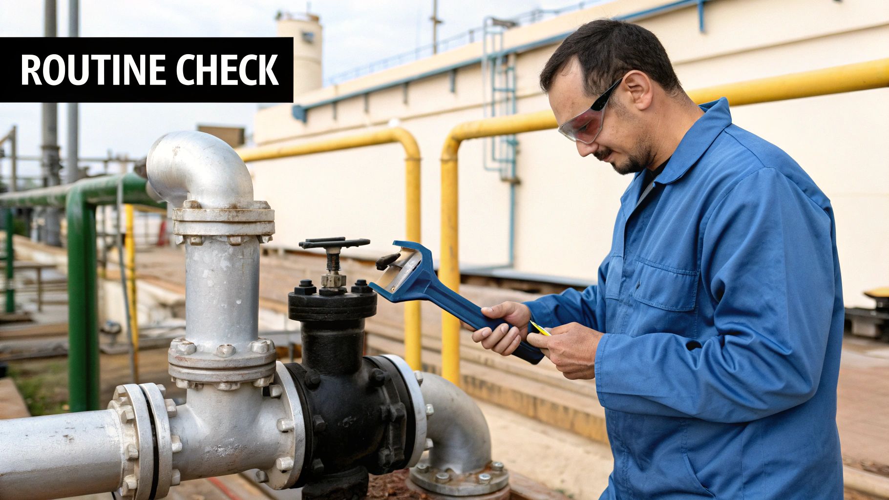
If a PRV is neglected, it can easily seize up due to corrosion, develop leaks, or its set pressure can drift over time. Your first line of defence is simple, routine visual checks. Maintenance teams should be on the lookout for any obvious signs of trouble – corrosion on the valve body, physical damage, or leaks from the seals. Spotting early warnings, like a bit of moisture build-up or faint hissing sounds, can stop a dangerous failure before it happens.
Proving Valve Reliability
Visual inspections are crucial, but they can’t tell you if the valve will open at the correct pressure. For that, you need proper testing, which usually falls into one of two camps. Each has its own place in making sure the valve is ready for action.
- Bench Testing: This is the most thorough approach. The PRV is carefully taken out of the system and moved to a workshop. It’s then mounted on a specialised test rig where its opening (set) pressure can be precisely checked and, if needed, adjusted.
- In-Situ Testing: Sometimes, taking a valve out of the line would cause major downtime or is just not practical. In these cases, in-situ (or in-place) testing is the way to go. This uses portable equipment to test the valve’s function without removing it from the system, making it a great option for continuous operations. This is often paired with advanced diagnostics to monitor how the valve is performing. To get the best data for these diagnostics, you need top-quality sensors. You can learn more in our guide on pressure transducers and how they support system monitoring.
Establishing a Testing Schedule
So, how often should you test? There’s no single answer. The right testing interval for a pressure relief valve depends entirely on its specific job and the regulatory standards you have to meet, like those from the Health and Safety Executive (HSE) in the UK.
A valve working in a clean, non-corrosive environment might only need testing every 5-10 years. In contrast, a valve in a highly corrosive or fouling service could need testing annually, or even more frequently, to guarantee its integrity.
Ultimately, a proactive maintenance schedule is the only way to be sure your PRV will do its job. It shifts the valve from being a passive component to a proven, trustworthy guardian. This rigorous approach ensures that when an emergency does happen, your last line of defence will hold strong, protecting your people, your plant, and your entire process.
Your Questions Answered: PRV Essentials
Even after getting to grips with the basics of how a pressure relief valve works, some very practical questions tend to pop up. Let's tackle some of the most common queries to clear up any confusion about key terms and safety practices.
What's the Difference Between a Relief Valve and a Safety Valve?
It's a common point of confusion, and while people often use the names interchangeably, there’s a crucial technical difference. It all comes down to how they open and what they’re designed to protect.
- A relief valve is designed to open gradually, in proportion to the pressure increase above its setpoint. Think of it as bleeding off excess pressure. This makes them the go-to choice for systems with incompressible fluids, like water or oil.
- A safety valve, in contrast, is all about immediate, decisive action. It has a rapid, full-lift "pop" action, opening completely almost instantly when it hits the set pressure. This is essential for compressible media like steam, air, or gas, where pressure can build explosively.
How Often Should a Pressure Relief Valve Be Tested?
There’s no single, one-size-fits-all answer here. The right testing frequency really depends on the job it’s doing and the environment it's in. You have to consider the service conditions, the type of fluid (is it clean or corrosive?), and, of course, any specific regulatory requirements.
As a rough guide:
- Critical or harsh services: Annual testing is a good bet. When failure is simply not an option, you need to know that valve is ready to go.
- Clean, non-corrosive services: You might be able to extend the interval to every 5-10 years.
Your first port of call should always be the manufacturer's recommendations and your own facility’s safety protocols, which ought to align with Health and Safety Executive (HSE) guidelines.
Can I Install a Shut-Off Valve Before a PRV?
In a word: no. Putting any standard isolation valve between the equipment you're protecting and its pressure relief valve is a major safety breach. If someone were to accidentally close that valve, the PRV would be completely cut off, leaving the system with zero protection against a catastrophic overpressure event.
If you absolutely must have a way to isolate the PRV for maintenance, it has to be done with a strictly controlled, purpose-built system. This usually means using interlocking valves or a very robust lock-out/tag-out procedure to make accidental closure impossible.
What Is "Blowdown" in a Pressure Relief Valve?
Blowdown is a vital performance metric. It’s simply the difference between the valve's set pressure (when it opens) and its reseating pressure (the lower pressure at which it closes again).
For instance, if a valve has a set pressure of 100 psi and a 7% blowdown, it will snap firmly shut once the system pressure falls back down to 93 psi. This gap is deliberately designed in. It stops the valve from "chattering"—rapidly opening and closing when the system pressure is just hovering around the setpoint. That kind of fluttering is incredibly damaging, so blowdown ensures a clean, decisive reseal once the danger has passed.
For expert technical support and a comprehensive selection of pressure control equipment, including relief valves, trust Solenoid Valve World. Explore our range of high-quality components designed for industrial, commercial, and municipal systems at https://solenoid-valve.world.