Solenoid Valve Wiring Diagram: From Confusion to Confidence
Understanding What Makes Solenoid Valves Tick
Let's be honest—staring at your first solenoid valve wiring diagram can feel a bit like trying to read a foreign language. Those lines and symbols are meant to bring clarity, but they often create more questions than answers at first glance. I’ve spoken with veteran technicians in fields from water treatment to industrial manufacturing, and a common theme emerges: the difference between an installation that lasts for decades and one that fails in months often boils down to a solid grasp of these fundamentals.
At its core, a solenoid valve is an electromechanical gatekeeper for fluids and gases. Think of it as a simple light switch, but instead of turning on a bulb, you're opening or closing a path for water, air, or oil. The 'switch' is flipped not by your hand, but by an electromagnet. When you send an electric current to the solenoid coil, it generates a magnetic field. This field pulls a small metal component, called a plunger or armature, which in turn opens or closes the valve's main opening, or orifice.
The Heart of the Machine: The Coil and Plunger
The relationship between voltage, current, and the valve’s performance is absolutely critical. A technician working on an HVAC system once told me about a stubborn issue where a valve would chatter or fail to open fully. The problem wasn't a faulty valve, but an underpowered circuit. The voltage was correct at the source, but the wiring gauge was too thin for the distance, causing a voltage drop that weakened the magnetic field. This is a classic example of how a perfect solenoid valve can fail because of an imperfect wiring plan.
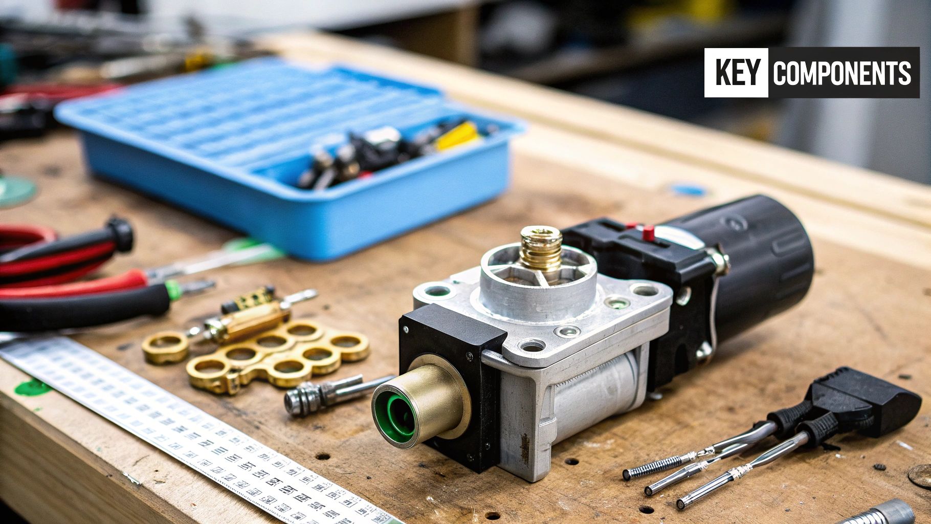
For a clearer picture, this diagram shows the basic components in action.
You can see the coil wrapped around the central plunger, which seals the orifice. When power is applied, the coil becomes a magnet, lifting the plunger and allowing flow.
Real-World Applications and Importance
This simple mechanism is the powerhouse behind countless automated systems. Here in the UK, solenoid valves are vital to major industries like water treatment and renewable energy production, where automation is key to efficiency. As investment in these automated technologies grows, so does the demand for reliable valves to control fluid flow electronically. This dependency highlights why understanding not just the valve, but the entire electrical circuit, is so important.
If you want to dive deeper into the basics of the component itself, you can learn more about what a solenoid valve is and how it works in our detailed guide. From a bottling plant ensuring every container is filled correctly to a natural gas system requiring fail-safe shutoffs, proper wiring isn't just about making things work—it's about safety, reliability, and preventing costly downtime.
Decoding Wiring Diagrams Like a Seasoned Pro
At first glance, the lines and symbols on a solenoid valve wiring diagram can feel like trying to read another language. But once you understand the basics, you'll see they tell a complete story about how the circuit works. Schematics from manufacturers like ASCO or Parker are packed with detail, and being able to interpret them lets you picture the entire system's operation before you even touch a wire. The clarity of these diagrams often comes down to good design, which shares principles with high-quality technical documentation. For those interested, exploring technical writing best practices can offer some fascinating insights into how clear communication is achieved.
Your first move should be to get comfortable with the fundamental symbols. Think of them as the alphabet of any electrical circuit.
Common Symbols and Their Meanings
Every line, circle, and squiggle on a diagram has a specific job, whether it's showing a power source or defining a type of connection. The image below, for instance, shows a collection of standard electronic symbols you're bound to see time and again.
This collection gives you a sense of how components like switches, grounds, and power sources are drawn, creating a universal shorthand for technicians everywhere. Being able to spot these symbols quickly is the first real step toward confidently tracing a circuit.
One of the most important distinctions you'll need to recognise is the difference between Normally Open (NO) and Normally Closed (NC) valve symbols. An NC valve's symbol shows a blocked path, meaning fluid can't flow when the valve is de-energised. Conversely, an NO valve's symbol shows a clear path, indicating it allows flow until it's energised. A veteran engineer once shared a simple but brilliant tip: he always uses a coloured pen to highlight the flow path on a complex diagram. It’s a small trick that can save a lot of confusion.
To help you get started, here's a quick-reference table breaking down the most common symbols you'll find on a solenoid valve wiring diagram.
Essential Solenoid Valve Wiring Symbols Decoded
Your quick reference guide to the most common symbols you'll encounter in solenoid valve diagrams, with practical explanations of what each one means for your installation.
| Symbol | Component Name | What It Controls | Installation Notes |
|---|---|---|---|
| Solenoid Coil | The electromagnetic part that, when energised, moves the valve plunger. | Ensure the coil voltage (e.g., 24V DC, 230V AC) matches your power supply. An incorrect match can destroy the coil. | |
| Normally Closed (NC) Valve | Flow through the valve. It remains shut until power is applied. | This is the most common type. Ideal for applications where the valve should be shut in a power failure (fail-safe closed). | |
| Normally Open (NO) Valve | Flow through the valve. It remains open until power is applied. | Used in systems where flow must continue during a power outage, such as certain cooling or venting applications. | |
| Switch (Manual or Automatic) | The flow of electricity to the solenoid coil. | This could be a simple toggle switch, a pressure switch, or an output from a PLC. It's the "trigger" for your valve. | |
| Fuse | Protects the circuit from overcurrent. | Always install a fuse with the correct amperage rating. It's a crucial safety component that protects the coil and wiring. | |
| Ground/Earth | Provides a safe path for fault currents to dissipate. | A proper ground connection is non-negotiable for safety, especially with mains voltage systems. |
This table acts as a great cheat sheet when you're on the job. Knowing these symbols by sight means you can quickly understand the function and safety features of any circuit you're working on.
Tracing the Circuit Path
Once you can recognise the key symbols, you can start following the flow of electricity. Always begin at the power source, which is usually shown as a battery symbol or an AC voltage symbol. From there, follow the lines to find the control component—this might be a switch, a thermostat, or a PLC output. This is the device that sends power to the solenoid coil.
The path will then lead to the coil itself (often drawn as a rectangle or a coiled line) and finally connect to the ground or neutral line, which completes the circuit. By tracing this entire path, you can check voltage requirements, spot safety devices like fuses, and identify potential trouble spots. For instance, in a large irrigation system, tracing the diagram might show that five separate valves are wired to a single controller output. This could easily overload the controller, leading to strange, intermittent failures. Spotting that kind of issue on paper before you start the installation is incredibly valuable.
Getting Your Toolkit Right for Professional Results
Having the right tools is what separates a frustrating afternoon of guesswork from a smooth, professional job. When you're tackling a solenoid valve wiring diagram, you don’t need a lorry full of expensive gear, but a few key items will save you from countless headaches. Let's skip the marketing fluff and look at what experienced technicians actually have in their bags.
The absolute heart of any electrical toolkit is a reliable multimeter. I always say it's your best mate for checking voltages, testing for continuity, and figuring out what's gone wrong. You don’t need the priciest one on the shelf, but make sure it has clear readouts for both AC/DC voltage and resistance – those are the essentials.
Essential Diagnostic Tools
While your multimeter might be the star of the show, a few supporting actors will make the work much safer and a whole lot easier. It's well worth adding these to your kit:
- Insulated Screwdrivers: This is a non-negotiable for safety, particularly when you're near 230V AC circuits.
- Wire Strippers and Crimpers: A clean strip and a secure crimp are the bedrock of any solid electrical connection. A good quality, all-in-one tool is a smart investment that pays for itself quickly.
- Voltage Tester Pen: This is a brilliant little device for a quick, non-contact check to see if a circuit is live before you lay a finger on it. It’s a simple tool that can prevent very serious accidents.
Here’s a look at a typical digital multimeter, which will be your main diagnostic tool.
The image shows the main dial you’ll use to switch between functions like voltage (V), current (A), and resistance (Ω), along with the ports for your test leads. Getting comfortable with these settings is fundamental before you start any electrical work.
Safety Gear That Actually Matters
Beyond the tools themselves, personal protective equipment (PPE) is something you can't afford to skip. While some job sites have long lists of requirements, the absolute basics for any solenoid valve task are safety glasses and the right pair of gloves. Insulated gloves are a particularly wise choice when dealing with higher voltages, as they provide a crucial extra layer of protection against electric shock.
At the end of the day, a well-organised toolkit with these essentials gives you the confidence to read any solenoid valve wiring diagram and bring it to life safely and accurately. It ensures your installation is not just working, but is robust and dependable from the moment you finish.
Getting Your Hands Dirty: The Installation Process
With the theory out of the way and your tools at the ready, it's time to translate that solenoid valve wiring diagram into a working reality. This is where your careful planning meets hands-on work. Surprisingly, the first and most critical step isn't about connecting wires—it's about calculating the circuit's load. Get this wrong, and you could face issues like voltage drop over long cable runs, which can cause the valve to perform poorly or even fail prematurely. I’ve personally seen this on large irrigation setups where a valve at the far end of a field just chatters uselessly because the power reaching it is too weak.
Following the Flow: Connection Sequence
Before you touch a single wire, always de-energise and lock out the power source. This isn't just a suggestion; it’s a non-negotiable step that separates a professional job from a dangerous one. The actual process of connecting the valve is quite logical, as you can see in the infographic below, which covers identifying, connecting, and insulating the wires.
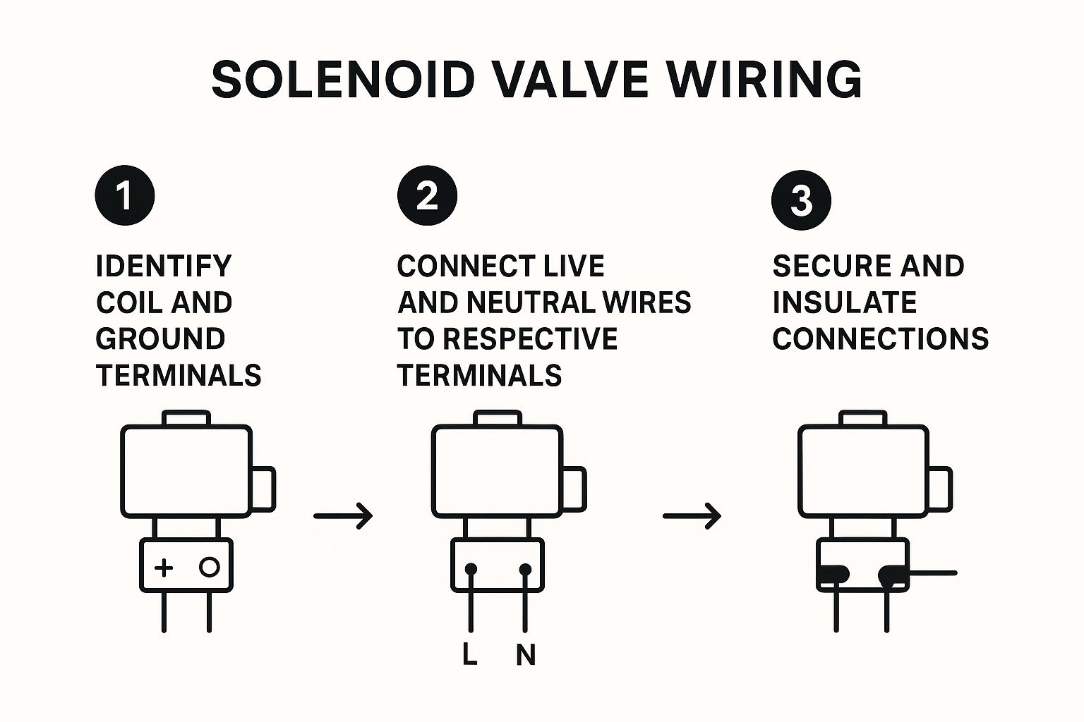
This visual guide breaks down the core steps, highlighting a clear sequence that helps ensure a solid connection from the very beginning.
Start by identifying the terminals on your solenoid coil. They’re usually marked, but if not, one is for the live/hot wire and the other is for the neutral. If your valve has an earth connection—which is essential for metal-bodied, mains-voltage valves—find that terminal first. Connect the earth wire securely. Next, connect the neutral wire, and finally, connect the live wire. Making the live connection last is a standard safety practice that minimises risk.
Routing Wires and Ensuring Durability
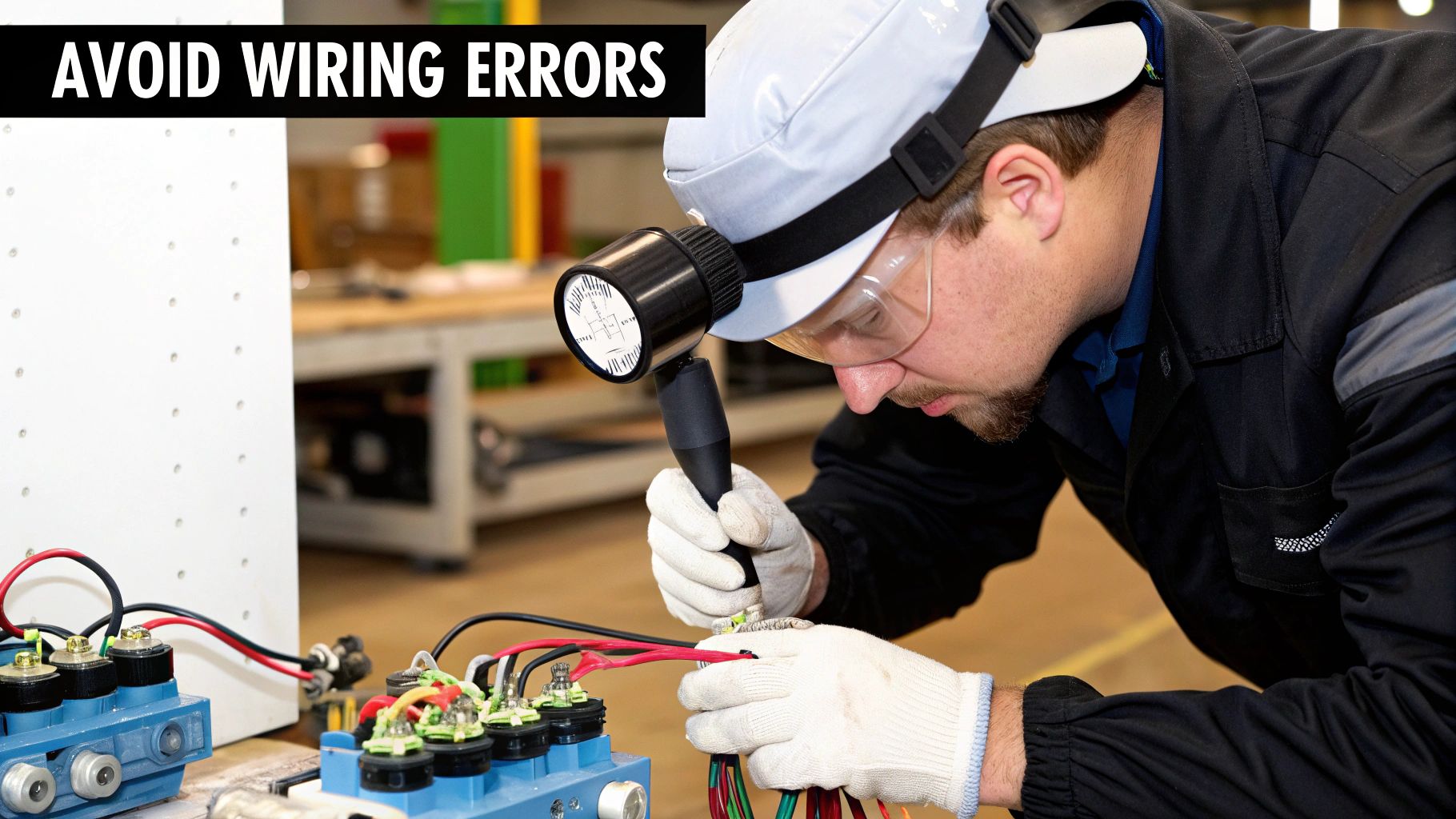
How you run your cables is just as vital as how you connect them. A neatly routed cable isn't just about aesthetics; it’s about preventing problems down the line. For a clearer idea of best practices in wiring, this image demonstrates several proper methods.
The image shows how organised cabling can protect wires from physical damage and heat sources. This is especially important in hydraulic systems where high pressures and temperatures are the norm. In fact, the hydraulic solenoid valve market is a massive part of the UK's fluid control industry. The global market was valued at around USD 3.2 billion in 2024 and is set to grow significantly. You can discover more about hydraulic solenoid valve market trends to understand why building robust installations is so important.
Once all connections are made and you've double-checked them against your diagram, it's time to test. For a complete walkthrough of testing and other crucial steps, have a look at our article on solenoid valve installations and maintenance instructions. Turn the power back on and activate the valve. You should hear a distinct "click" as the plunger moves. If you hear buzzing or chattering instead, shut off the power immediately and start troubleshooting—it often points back to a voltage drop or a loose connection.
Choosing the Right Wiring Setup for Your Situation
Not every job calls for the same wiring approach, and honestly, this is where you can save yourself a lot of hassle and money. The solenoid valve wiring diagram for a single valve on a compressed air line in a small workshop will look worlds apart from one for a multi-valve manifold in a large manufacturing plant. Making the right choice upfront comes down to balancing simplicity, cost, and future flexibility.
For instance, a direct-wired configuration is often the go-to for straightforward, standalone applications. Think of a simple irrigation system for a single garden zone or a basic fluid dispensing station. Here, you simply run wires directly from your power source, through a switch or controller, to the solenoid coil. It’s cheap, easy to troubleshoot with a multimeter, and perfectly reliable for isolated tasks.
The major drawback, however, is a lack of scalability. If you suddenly need to add ten more valves, you’ll find yourself running a messy and expensive web of individual cables back to your control point. This is where a bit of foresight really pays off.
Comparing Common Setups
On the other end of the spectrum, you have networked or bus systems, such as those using AS-Interface (AS-i) or IO-Link. These are common in advanced automation, like in a modern bottling plant or a sophisticated water treatment facility. Here, multiple valves are connected to a local I/O block, which then communicates back to a central PLC over a single network cable.
The initial investment is higher, and it requires more specialised knowledge. The huge benefit, though, is how clean and expandable the system is. Adding a new valve can be as simple as plugging it into the nearest block. This setup also provides rich diagnostic data, telling you if a valve has failed without you needing to test it manually.
To help you decide which path makes the most sense for your project, I've put together a quick comparison of the most common approaches.
Wiring Configuration Quick Comparison Guide
Compare different solenoid valve wiring setups to find the best approach for your specific application, with honest assessments of pros, cons, and costs.
| Setup Type | Best For | Main Benefits | Potential Drawbacks | Budget Range |
|---|---|---|---|---|
| Direct Wiring | Simple, single-valve or small-group installations. Standalone machines. | Low initial cost, easy to understand and troubleshoot. | Becomes messy and costly to scale up, no advanced diagnostics. | £ |
| Terminal Block | Medium-sized systems (5-20 valves) centralised in one cabinet. | Keeps wiring organised in one place, easier to manage than direct wiring. | Requires cabinet space, can still be labour-intensive to wire initially. | ££ |
| Networked (Bus System) | Large, complex automation with many valves. Systems needing diagnostics. | Drastically reduces cabling, highly scalable, provides detailed feedback. | Higher initial cost, requires programming and specialised knowledge. | £££ |
As you can see, choosing your setup is a balancing act. A simple direct-wire job is perfect for a quick, low-cost fix, but a networked system offers unparalleled control and scalability for larger operations. Consider not just your immediate needs but also where the system might be in five years. A bit of extra planning now, guided by a clear understanding of the options, prevents major headaches and rewiring jobs down the line.
When Things Go Wrong: Smart Troubleshooting Approaches
Even with the most perfectly drawn solenoid valve wiring diagram, you'll eventually run into a snag. The real skill isn't in preventing every possible problem, but in diagnosing them logically when they pop up. A seasoned technician knows that blindly swapping parts is a waste of time and money. It's easy to blame the valve itself, but more often than not, the fault lies somewhere else in the circuit.
I remember a classic case with a dust-collection system where a key valve just wouldn't open. The wiring diagram was spot on, the controller was definitely sending the signal, but the valve remained shut. Instead of immediately replacing it, we went back to basics. A quick check with a multimeter at the coil terminals gave us a reading of 18V AC, not the 24V AC it needed. By tracing the cable back, we discovered a loose connection in a junction box that was causing a serious voltage drop. It was a simple fix, but we only found it by working methodically from the problem back to the source.
A Systematic Diagnostic Flow
When a valve starts acting up, your goal should be to find the root cause, not just patch the symptom. This ensures the problem doesn't come back to haunt you. A smart diagnostic approach saves a lot of headaches.
Here’s a practical flow to follow:
- Visual Inspection: Before you even reach for your tools, just have a proper look. Can you see any obvious signs of trouble like corrosion, frayed or loose wires, or physical damage to the coil or its housing? Sometimes the problem is staring you right in the face.
- Check the Power: Is the control system actually doing its job? Grab your multimeter and confirm that the correct voltage is reaching the coil terminals when the valve is supposed to be active. No voltage means the problem is further upstream.
- Continuity and Resistance: With the power safely off, test the coil's resistance. An infinite reading tells you the coil wire is broken (an open circuit), while a zero reading points to a short circuit. In either case, the coil is faulty and needs replacing.
- Mechanical Issues: Don't forget that the problem might not be electrical at all. It's possible for debris to clog the orifice, or for an internal seal to have worn out over time. If you suspect a seal issue, our guide on solenoid valve seal materials can be a great help in figuring out if the right material was used for the job.
Mastering this kind of systematic process is becoming more crucial. The UK solenoid valve market is projected to grow with a compound annual growth rate of about 4.3% between 2025 and 2035, partly thanks to new sustainability initiatives. You can read more on these market projections to see why efficient maintenance and troubleshooting skills are so valuable. For a more general approach to fault-finding, this expert technical troubleshooting guide also has some excellent pointers.
Professional Insights for Long-Term Success
The real difference between a job that just works and one that stands the test of time often lies in the details you won't find in a standard manual. These are the lessons you learn from years of hands-on work with complex systems. For instance, one of the most common pitfalls when creating a solenoid valve wiring diagram is forgetting about electromagnetic interference (EMI), especially in facilities buzzing with variable frequency drives (VFDs) and other noisy electrical equipment.
Advanced Protective Measures
To tackle EMI, seasoned pros will often use shielded cabling for all the control wiring. The key trick is to make sure the shield is earthed at one end only—usually at the control panel. This simple step prevents ground loops and can be the difference between a valve that operates smoothly and one that chatters or fails without warning.
Proper earthing is another area where experience really shows. In a damp or corrosive environment, just hooking up to the nearest bit of metal framework won't cut it. You need a dedicated earth rod or a solid connection to a verified main earthing terminal (MET) to guarantee both safety and reliable performance.
Documentation and Future-Proofing
Your work isn't over once the valve is up and running. To ensure long-term success, you need to think ahead.
- Detailed As-Built Diagrams: Always go back and update your original wiring diagram to show exactly how it was installed. Make notes of cable lengths, where the cables run, and any changes you had to make on the fly.
- Preventive Maintenance Schedules: Don't wait for something to break. Set up a schedule for periodic checks on connection tightness, the condition of the insulation, and the coil's resistance. A coil showing a 10-15% change from its original resistance is often a clear warning that failure is on the horizon.
- Strategic Upgrades: Keep an ear to the ground for new technology. Modern smart valves can offer diagnostic feedback, which makes any future troubleshooting much quicker and easier.
Thinking beyond the immediate installation ensures your work stays robust, safe, and easy for someone else to maintain for years to come.
For a comprehensive selection of valves built for reliability, from WRAS-approved models to ATEX-certified solutions, feel free to explore our range at Solenoid Valve World.