Mastering the Valve Flow Coefficient Cv and Kv
Think of the valve flow coefficient (Cv) as a simple, standardised rating for how much fluid a valve can handle. A higher Cv value is like a wider motorway—it allows more traffic (fluid) to pass through with less congestion (resistance). A low Cv is more like a narrow country lane.
This single number tells you everything you need to know about a valve's flow capacity at a glance.
Why the Valve Flow Coefficient Is So Important
Imagine trying to design the heating system for a new hospital without knowing how much hot water the radiators or pipes could handle. You might end up with freezing cold rooms on the top floor or, just as bad, install oversized, expensive pipework that was never needed. This is exactly the chaos the valve flow coefficient was created to prevent.
It gives engineers a reliable, universal number to work with, allowing for a straightforward comparison between different valves, no matter their size, brand, or internal design.
In short, the flow coefficient cuts out the guesswork. It turns a complex fluid dynamics puzzle into a simple exercise of matching the right number to the system's requirements.
Without it, we'd be back in the dark ages of trial and error, leading to inefficient systems, wasted energy, and the constant risk of equipment failure. A solid grasp of this coefficient is fundamental for anyone working with fluid control, from water treatment plants to diverse manufacturing and industrial applications.
Defining Cv and Its Metric Partner, Kv
While the idea is universal, the measurement itself comes in two main flavours: Cv (Imperial) and Kv (Metric). Think of it like miles and kilometres—they both measure distance, just using a different scale.
- Cv (Flow Coefficient): This is the Imperial standard, common in the US. It's defined as the volume of water in US gallons per minute (GPM) that can pass through a valve with a pressure drop of 1 pound per square inch (psi).
- Kv (Flow Factor): This is the Metric standard you'll find throughout the UK and Europe. It measures the volume of water in cubic metres per hour (m³/h) flowing through a valve with a pressure drop of 1 bar.
They both do the same job—quantifying a valve's flow capacity—but it's crucial to know which one you're working with, especially when dealing with international projects or specifications.
In UK engineering, the Cv value is still a go-to parameter for sizing control valves correctly. Historically based on Imperial units, it underpins the design of countless pump and valve systems, ensuring they run efficiently and reliably. For context, a small needle valve might have a Cv below 1, whereas a large 1-inch ball valve could have a Cv of around 80, showing its high flow efficiency. A globe valve of the same size, designed for more precise control, might have a Cv closer to 10, indicating its more restrictive nature.
Cv vs Kv At a Glance
To make things even clearer, here's a quick side-by-side comparison of the two main flow coefficient standards. This table breaks down their units and definitions for easy reference.
| Parameter | Cv (Imperial) | Kv (Metric) | Key Takeaway |
|---|---|---|---|
| Primary Unit of Flow | US Gallons per Minute (GPM) | Cubic Metres per Hour (m³/h) | Cv is based on the Imperial system, while Kv is its Metric counterpart. |
| Pressure Drop Unit | 1 Pound per Square Inch (psi) | 1 Bar | This is the standard pressure difference used for the measurement test. |
| Standard Fluid | Water at 60 °F (15.6 °C) | Water at 5-30 °C | Both standards use water as the reference fluid for consistent testing. |
| Common Region | United States | UK, Europe, and most of the world | Your project's location and specifications will dictate which unit you use. |
Although the numbers look different, remember that Cv and Kv are simply two dialects of the same language—the language of flow. Knowing how to interpret and convert between them is a key skill for any engineer in the field.
Calculating the Flow Coefficient for Liquids
Understanding the theory behind the valve flow coefficient is one thing, but calculating it is where knowledge turns into practical skill. For liquids like water, which we treat as incompressible, the process is thankfully quite straightforward. It all comes down to a standard formula that connects flow rate, pressure, and the fluid's properties into a single, actionable number.
This calculation is the absolute cornerstone of valve sizing. Get it right, and your system performs beautifully and efficiently. Get it wrong, and you're in for a world of operational headaches, from not getting enough flow to creating damaging system pressures.
The Standard Formula for Liquids
The relationship between the valve flow coefficient (Cv), flow rate (Q), pressure drop (ΔP), and specific gravity (SG) is defined by a simple but powerful formula.
Here is the standard equation you'll use for any liquid application:
Cv = Q x √(SG / ΔP)
Let's break down what each of these components means in a real-world system:
- Q (Flow Rate): This is the volume of liquid you need to move through the valve in a set amount of time. It's typically measured in US Gallons Per Minute (GPM).
- SG (Specific Gravity): This tells you how dense your fluid is compared to water. For water itself, the SG is a handy 1.0, which simplifies things nicely. For other fluids, like certain oils or glycols, you'll need to plug in their specific SG value.
- ΔP (Pressure Drop): This is the difference in pressure between the inlet and the outlet of the valve, measured in pounds per square inch (psi). It represents the "work" the valve has to do to control the flow.
Using this formula lets you pinpoint the exact Cv value needed to hit your target flow rate under your system's specific pressure conditions.
Key Insight: The pressure drop (ΔP) isn't just a number; it's a critical design choice. A higher pressure drop lets you use a smaller, often less expensive valve, but it forces your pump to work harder. Finding that sweet spot is key to an efficient and cost-effective system.
A Practical Calculation Example
Theory is a great start, but let's walk through a real-world scenario to see how this all fits together.
Scenario: An industrial process needs a control valve for a chilled water cooling loop.
- Required Flow Rate (Q): 150 GPM
- Fluid: Chilled Water (so, Specific Gravity (SG) is 1.0)
- Inlet Pressure (P1): 80 psi
- Required Outlet Pressure (P2): 75 psi
Step 1: Calculate the Pressure Drop (ΔP) First up, we need to find the pressure difference across the valve.
ΔP = P1 - P2 ΔP = 80 psi - 75 psi ΔP = 5 psi
Step 2: Plug the Values into the Cv Formula Now we have all the pieces of the puzzle. Let's put them into the formula.
Cv = Q x √(SG / ΔP) Cv = 150 x √(1.0 / 5) Cv = 150 x √(0.2) Cv = 150 x 0.447 Cv = 67.05
Based on this, you'd need to shop for a valve with a Cv rating of at least 67.05. This precise number gives you the confidence to compare different valve models and select one that is perfectly sized for the job.
Common Pitfalls to Avoid
While the formula itself is simple, small mistakes can cause big problems down the line. Keep an eye out for these common errors:
- Mixing Units: Make absolutely sure your flow rate is in GPM and your pressure is in psi. Using other units without converting first will throw your result way off.
- Miscalculating Pressure Drop: Always use the pressure drop across the valve itself, not the total pressure drop for the entire system. It's a very common mix-up.
- Forgetting Specific Gravity: If you're working with any fluid other than water, forgetting to use the correct SG will lead to an incorrectly sized valve.
Accurately calculating the valve flow coefficient is a fundamental skill for anyone in this field. It's also worth knowing that you can rearrange the formula to solve for other variables. For instance, you can work out the flow rate if you already know the pressure drop, which is incredibly useful for analysing existing systems.
To dig deeper into that, check out our helpful guide on how to calculate flow rate from pressure.
Handling Calculations for Gas and Steam

When you move from liquids to gases or steam, you're playing a whole new ball game. The simple rules for calculating the valve flow coefficient go out the window. Unlike water, which is practically incompressible, gases and steam are compressible fluids. This means their density changes dramatically with any shift in pressure and temperature, throwing a few more crucial variables into the mix.
Nailing the correct valve flow coefficient for these media isn't just about plugging numbers into a different formula. It's about really understanding the physics of how a gas behaves under pressure. As it zips through a valve from a high-pressure zone to a low-pressure one, it expands. This expansion completely changes the flow dynamics, and you absolutely must account for it to size a valve correctly.
Get it wrong, and you're in for a world of trouble. An undersized valve will starve the system, while an oversized one will give you poor control and waste energy. The formulas are naturally a bit more complex, bringing in factors like upstream pressure and absolute temperature to get a true picture of the valve's performance.
Understanding the Formulas for Gas and Steam
Because gases and steam expand as pressure drops, we need more information than just the flow rate and pressure differential. The calculations have to consider the initial conditions before the gas even reaches the valve. While there are a few different formulas depending on the exact conditions, they all hinge on the inlet pressure, temperature, and the specific gas you're working with.
For what we call non-critical pressure drop situations (where the outlet pressure is more than half the inlet pressure), a common formula for gas flow is:
Cv = Q / (1360 x √((P1 - P2) x P2) / (SG x T))
Let's break down those new terms:
- Q: Flow rate, typically measured in Standard Cubic Feet per Hour (SCFH).
- P1: Inlet (upstream) absolute pressure in psia.
- P2: Outlet (downstream) absolute pressure in psia.
- T: Absolute temperature of the gas in Rankine (°F + 460).
- SG: Specific Gravity of the gas (with Air = 1.0).
This formula really shows how vital the absolute pressures and temperature are. They directly influence the gas's density and how it will behave as it squeezes through the valve.
The Critical Concept of Choked Flow
Now for one of the most important things to get your head around when working with gases: choked flow. You might also hear it called critical flow, and it’s a phenomenon that simply doesn't happen with liquids.
Choked flow occurs when the gas velocity through the valve's narrowest point (the vena contracta) reaches the speed of sound. At this point, lowering the downstream pressure further will not increase the flow rate. The valve is essentially maxed out, and the flow is "choked."
This usually happens when the outlet pressure (P2) drops to about 50-55% of the inlet pressure (P1). Ignoring choked flow is a classic and major design flaw. If your system needs a higher flow rate than what the choked condition allows, no amount of fiddling with the downstream pressure will help. Your only options are to increase the upstream pressure or, more likely, select a valve with a higher Cv.
Practical Calculation Examples
Let's put this into practice and see how you'd determine the valve flow coefficient in a couple of common scenarios.
Example 1: Compressed Air System
- Fluid: Compressed Air (SG = 1.0)
- Flow Rate (Q): 5,000 SCFH
- Inlet Pressure (P1): 100 psig (114.7 psia)
- Outlet Pressure (P2): 90 psig (104.7 psia)
- Temperature: 70°F (530 °R)
First, let's check for choked flow. P2 (104.7 psia) is much higher than 50% of P1 (57.4 psia), so we're safe. The flow is not choked.
Cv = 5000 / (1360 x √((114.7 - 104.7) x 104.7) / (1.0 x 530)) Cv = 5000 / (1360 x √(1047 / 530)) Cv = 5000 / (1360 x √1.975) Cv = 5000 / (1360 x 1.405) Cv = 5000 / 1910.8 Cv = 2.62
For this system, you would need to select a valve with a Cv of at least 2.62.
Example 2: Process Steam Line
With saturated steam, we often use a slightly different formula that's based on the weight of the steam in pounds per hour.
- Required Flow: 800 pounds per hour (lb/hr)
- Inlet Pressure (P1): 150 psig (164.7 psia)
- Outlet Pressure (P2): 120 psig (134.7 psia)
The pressure drop here is 30 psi. Since P2 is well above 50% of P1, we are in non-critical flow. A common simplified formula for this situation is:
Cv = W / (3 x √(P1 - P2) x P2) Where W is the flow rate in lb/hr.
Cv = 800 / (3 x √(30 x 134.7)) Cv = 800 / (3 x √4041) Cv = 800 / (3 x 63.5) Cv = 800 / 190.5 Cv = 4.20
In this steam application, you would need to source a valve with a Cv of at least 4.20.
Converting Between Cv and Kv for Global Projects

In our interconnected world, engineering projects rarely happen in a bubble. It's common to see components and specifications cross borders, which means you need to be fluent in both the Imperial (Cv) and Metric (Kv) flow coefficient standards. It's no longer just a nice-to-have skill; it's essential.
Imagine this: you've sourced a perfect valve from a European manufacturer, but its datasheet lists a Kv value. Your entire system, however, has been designed and calculated using Imperial units in the UK. Being able to translate between these two "dialects" of flow measurement is what prevents costly mismatches and poor system performance. Thankfully, the conversion is incredibly simple.
The Conversion Formulas You Need to Know
The relationship between the Imperial valve flow coefficient (Cv) and the Metric flow factor (Kv) is just a fixed ratio. If you can remember two simple formulas, you can convert any value in seconds and bridge the gap between international datasheets.
To find Kv when you know Cv: Kv = 0.865 × Cv
To find Cv when you know Kv: Cv = 1.156 × Kv
These multipliers neatly handle the differences in units—gallons per minute versus cubic metres per hour, and psi versus bar—that define each coefficient.
Key Takeaway: Think of these formulas as your universal translator for valve specifications. They empower you to confidently compare a valve from a German supplier with one from an American firm, ensuring you're always making a true like-for-like comparison.
A Quick Conversion Example
Let's walk through a real-world scenario to see how easy this is. You're reviewing specs for a control valve made in Germany, and the datasheet clearly states its flow factor is Kv = 40. All your project calculations are based on the Imperial system, so you need the equivalent Cv value to see if it fits.
1. Select the Correct Formula You have the Kv and need to find the Cv, so you'll use this formula: Cv = 1.156 × Kv
2. Perform the Calculation Now, just slot the known Kv value into the equation: Cv = 1.156 × 40 Cv = 46.24
It’s that straightforward. A valve rated with a Kv of 40 is equivalent to one with a Cv of 46.24. You can now confidently decide if this European valve meets your system's requirements without any guesswork.
Why Kv Is a UK Standard
While the UK famously uses a mix of Imperial and Metric, the Kv value has become the dominant standard in sectors like building services, HVAC, and district heating. This is largely down to the strong influence of European standards and regulations, which are heavily focused on boosting energy efficiency. The valve flow coefficient is fundamental to the performance of these systems.
For instance, in a large UK commercial building, the Kv value for heating circuit valves can range from 1 m³/h for a small radiator control up to 20-30 m³/h for main system valves. Getting this right is critical; studies have shown that a poorly matched valve flow coefficient can lead to system inefficiencies of over 10%, causing significant fuel waste and higher running costs. To dig deeper into how these values impact modern system design, you can find excellent insights on Kv and Kvs values on grundfos.com.
How to Select the Perfect Valve Using Cv
You've done the calculations and have your magic number—the required valve flow coefficient. But just holding this Cv value is like having the right key without knowing which door it opens. The next crucial step is selecting the perfect valve, and it's about much more than just matching a number on a datasheet.
Simply picking a valve with a Cv that meets your calculated requirement isn't good enough. You could still end up with a component that performs poorly, wears out quickly, or just wastes energy. The real secret to great system control lies in understanding how a valve delivers that flow.
Beyond Cv: The Role of Flow Characteristics
Valves, even with identical Cv ratings, don't behave the same way. The relationship between how much you open the valve (its stem travel) and the resulting flow rate is known as its flow characteristic. Getting this right is vital for achieving stable and precise process control.
The three main flow characteristics you'll encounter are:
- Linear: The flow rate is directly proportional to how much the valve is open. Opening the valve by 20% gives you 20% of the flow. This is ideal for systems where the pressure drop across the valve stays fairly constant.
- Equal Percentage: Every increment of valve opening creates an equal percentage change in the existing flow. This type of valve gives you fine control at low flow rates and handles big changes in system pressure extremely well, making it a favourite for many control applications.
- Quick Opening: A large amount of flow rushes through with just a small amount of initial opening. These are best for on/off services where you need to get things moving fast, but they are a poor choice for throttling or precise control.
This image shows how the internal design of different valves affects their flow capacity, even if they're for the same pipe size.
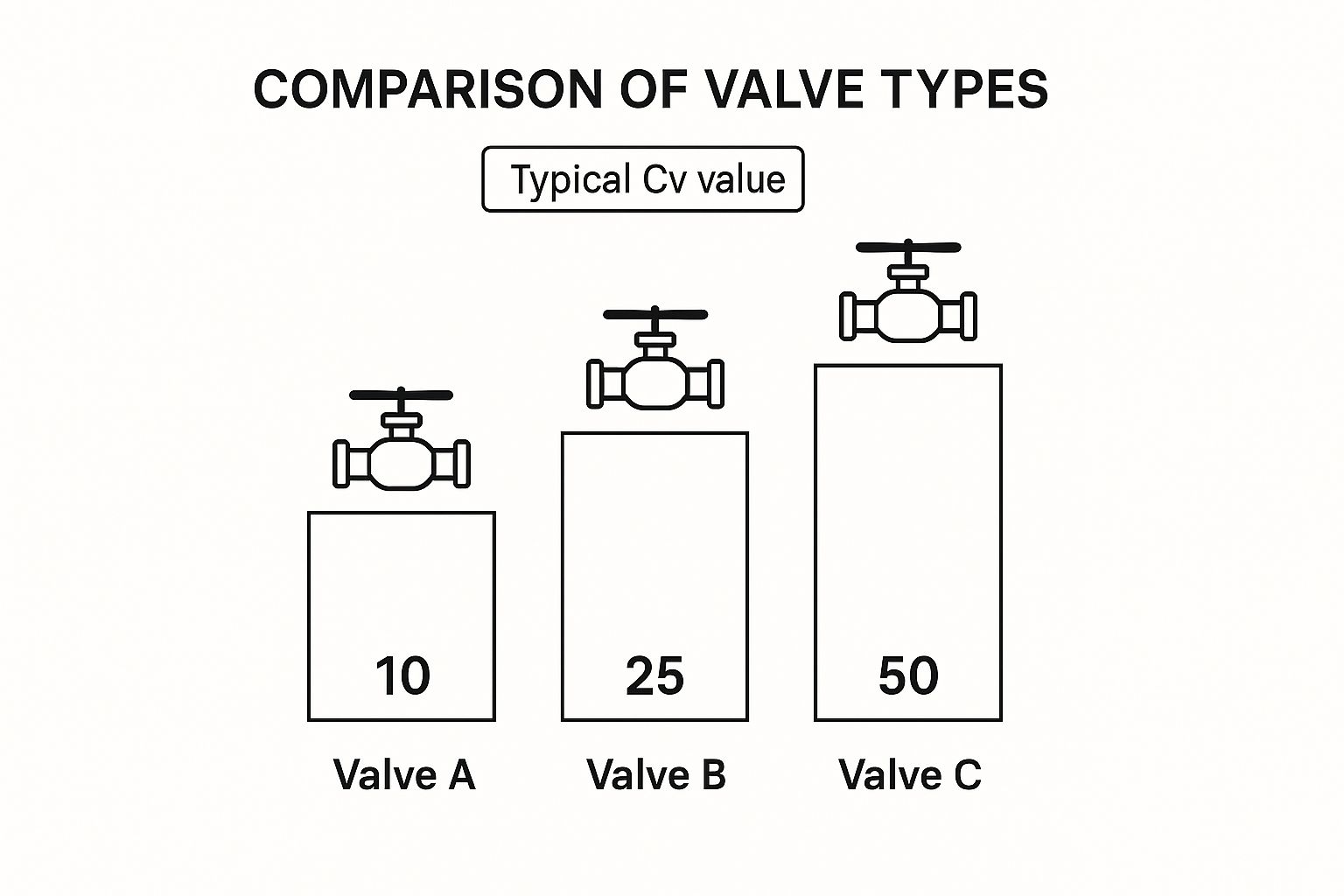
As you can see, a valve designed for minimal obstruction, like a ball valve, will naturally have a much higher flow coefficient than one built for fine control, such as a globe valve.
Valve Type Selection Guide
To help you navigate these differences, the table below provides a quick overview of common valve types, their flow behaviours, and where they work best.
| Valve Type | Flow Characteristic | Typical Cv Range | Best Use Cases |
|---|---|---|---|
| Ball Valve | Quick Opening | High | On/off isolation, high flow systems |
| Globe Valve | Linear or Equal % | Low to Medium | Throttling, precise flow control |
| Butterfly Valve | Approx. Equal % | Medium to High | Throttling, large pipe diameters |
| Gate Valve | Quick Opening | Very High | Fully open or fully closed isolation |
| Needle Valve | Modified Linear | Very Low | Extremely fine, low-flow control |
Choosing the right type is the first step towards a well-behaved and efficient system.
The Dangers of Oversizing a Valve
One of the most common—and costly—mistakes we see is choosing a valve that is too large for the job. It might feel like a safe bet to have extra capacity "just in case," but this almost always leads to serious problems down the line. An oversized valve is a troublemaker.
Because its Cv is too high, the valve will only need to open a tiny fraction—maybe just 5-10%—to hit your target flow rate. This creates two major issues:
- Poor Control: Trying to make tiny adjustments in such a narrow operating window is nearly impossible. Your system will constantly overshoot and undershoot the setpoint, a frustrating condition known as ‘hunting’.
- Rapid Wear: The high-velocity fluid blasting through a barely open valve causes intense erosion and vibration, quickly destroying the valve's seat and plug.
The industry best practice is to select a valve where your required Cv falls comfortably in the middle of its operational range. Aim for a valve that will be 50% to 80% open at your normal operating flow rate. This gives you the best control, stability, and longest service life.
This principle of matching capacity to demand is also vital for safety components. You can learn more about how they work by exploring our range of pressure relief valves.
Common Valve Sizing Questions Answered
Even when you have a good handle on the formulas and selection rules, practical questions always pop up out in the field. When you're specifying a new valve or trying to figure out what's wrong with an existing system, understanding the nuances of the flow coefficient is what really matters.
Let's walk through some of the most common questions and points of confusion that engineers and technicians run into. Getting these details right can be the difference between a smooth, efficient system and one that’s constantly fighting itself and wearing out too soon.
What If My Chosen Valve Cv Is Too High or Too Low?
Picking a valve with the wrong flow coefficient is one of the most common mistakes in the book, and it’s a fast track to all sorts of operational headaches. Whether it’s too big or too small, you're going to have problems.
A Cv that is too high means the valve is simply too big for the job. To hit your target flow rate, it will only need to crack open a tiny bit. This creates a couple of big issues:
- Poor Control: The system becomes incredibly twitchy. The slightest movement of the actuator causes a huge jump in flow, making it almost impossible to hold a steady setpoint. Engineers often call this 'hunting'.
- Accelerated Wear: Think of high-pressure fluid blasting through a tiny opening. This causes intense erosion and vibration, which can quickly chew up the valve's seat and plug, leading to leaks and a much shorter service life.
On the other hand, a Cv that is too low means the valve is undersized. It's like trying to drink a thick milkshake through a coffee stirrer. Even when it's fully open, it just can't pass enough fluid. This starves the system, creates a massive and unintended pressure drop, and can even cause damaging effects like cavitation or flashing, where the liquid actually boils inside the valve.
The sweet spot is to choose a valve that gives you the flow you need when it's between 50% and 80% open. This puts the valve right in its most stable and responsive control range, giving you the best performance and a much longer life.
Does the Valve Type Affect the Cv Value?
Absolutely. The physical design and internal geometry of a valve are what fundamentally determine how much fluid it can pass. For the exact same pipe size, different valve types will have wildly different Cv values.
Just picture the path the fluid has to take. A full-bore ball valve, when open, offers a straight, almost completely unobstructed path. This minimal resistance gives it a very high flow coefficient, making it perfect for simple on/off jobs where you just want maximum flow.
A butterfly valve also provides a relatively high flow, though the disc in the centre always creates a little more resistance than an open ball valve.
A globe valve is the complete opposite. It's designed to create resistance by forcing the fluid through a winding, S-shaped path. This makes it fantastic for precise throttling and flow control, but it results in a much lower Cv value compared to a ball or butterfly valve of the same size. Understanding how a valve's internal design serves its function is key. You can see this principle in action by looking at other components like our range of check valves, which are built for the very specific purpose of allowing flow in only one direction.
How Does Fluid Viscosity Change the Calculation?
Standard Cv and Kv calculations are all based on one thing: water. Water has a very low viscosity, meaning it flows very easily. The moment you start working with thicker, more viscous fluids like oils, syrups, or heavy chemicals, those standard formulas go out the window.
Higher viscosity is like internal friction. It makes the fluid resist flowing, which effectively chokes off the valve's capacity. If you use a standard water-based calculation for a thick oil, you will almost certainly end up with an undersized valve that can't do its job.
To get it right, you have to apply a viscosity correction factor (Fv) to your initial Cv calculation. This factor adjusts the figure to account for the extra push needed to get the thicker fluid through the valve.
These correction factors aren't just guesses; they are determined through extensive testing and can be found in:
- Engineering handbooks and manuals.
- Technical datasheets from valve manufacturers.
- Specialised valve sizing software.
The right factor depends on the fluid's viscosity (usually measured in Centistokes), the pipe size, and the flow conditions. Skipping this step is a recipe for system failure.
Can I Use the Cv Value to Estimate Pressure Drop?
Yes, and this is an incredibly practical way to use the flow coefficient, especially when you're troubleshooting an existing system. The standard formula for liquids can be easily flipped around to solve for pressure drop (ΔP) if you know the other values.
The rearranged formula is simple:
ΔP = SG x (Q / Cv)²
Here’s why that’s so useful. Imagine a part of your system is underperforming, and you suspect a control valve is causing too much of a pressure loss.
If you can measure the actual flow rate (Q) through the pipe, and you know the valve's published Cv (from its datasheet) and the fluid's specific gravity (SG), you can calculate the real-world pressure drop it's creating. This lets you diagnose problems without just guessing.
For example, if your calculation shows the valve is causing a 20 psi drop but the design only allowed for a 5 psi drop, you’ve just found a major source of inefficiency. The cause could be a partially blocked valve, the wrong valve being installed, or some other internal damage. It’s a powerful tool for pinpointing issues with real data.
At Solenoid Valve World, we provide the technical expertise and extensive product range you need to select the perfect valve for any application. From standard water systems to complex industrial processes, our UK-based team is here to help you get it right. Explore our comprehensive selection at https://solenoid-valve.world.