Ultimate Pneumatic System Design Guide: Build Reliable Systems
Diving into pneumatic system design might seem a little daunting at first, but it all comes down to a simple idea: using compressed air to make things happen. It’s not much different from a bicycle pump inflating a tyre—you're just channelling that air pressure to create controlled movement. This guide is here to walk you through it, turning theory into practical steps for building systems that are both reliable and efficient.
Why Pneumatic Systems Are a Cornerstone of Modern Industry
Pneumatic systems are the unsung heroes of the industrial world, working tirelessly behind the scenes in everything from huge factory assembly lines to the handheld tools a mechanic uses. The magic lies in their simplicity. By using controlled, compressed air to do useful work, they offer a fantastic blend of reliability, safety, and cost-effectiveness that few other technologies can match.
And they’re not going anywhere. If anything, their importance is growing as more industries lean into automation. In the UK, for instance, the market for pneumatic conveying systems is expected to see strong growth between 2025 and 2031. This isn’t surprising when you consider the demand for clean, efficient material handling in sectors like food production and pharmaceuticals, where pneumatics reduce contamination risks and boost safety. You can get the full picture in the research report on pneumatic conveying systems.
The Sheer Versatility of Compressed Air
When you start designing your own pneumatic system, it helps to think about where this technology truly shines. The applications are incredibly varied, which really shows how adaptable compressed air can be.
You’ll find pneumatic systems hard at work in:
- Manufacturing and Assembly: Powering pick-and-place robots, clamping parts firmly for machining, and operating massive presses.
- Food and Beverage: Gently moving products along conveyor belts and running packaging machines in sterile environments.
- Pharmaceuticals and Medical: Enabling the precise, delicate movements needed in lab equipment and medical devices.
- Automotive: Operating everything from air brakes on lorries to the power tools on the production line and even paint sprayers.
This wide-ranging utility is a testament to the practical power of pneumatics. Once you grasp the core principles we'll cover, you'll start to see how they fit into different application sectors and how you can tailor a system to solve almost any operational challenge.
Key Takeaway: The foundation of any good pneumatic design is having a crystal-clear understanding of the job it needs to do. Before you even think about picking components, you have to define what the system must achieve, how fast it needs to work, and how much force it has to generate.
With that foundation laid, you're ready to move on. We've covered the "why" of pneumatic technology; now we can get into the "how" of designing, selecting parts, and making the right calculations.
Understanding the Core Pneumatic Components
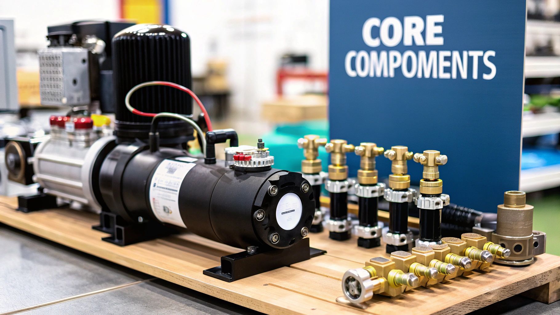
Every pneumatic system, no matter how complicated it seems, is really just a collection of core parts working in harmony. It helps to think of it like an orchestra; each instrument has its part to play, but it’s how they work together that creates the music. Getting to grips with what each component does is the first step to designing a system that’s both effective and reliable.
This isn't just theory—it's the bedrock of any solid pneumatic system. The sheer size of the global market for these parts tells its own story. Valued at USD 14.4 billion in 2024, the pneumatic components market is expected to climb to over USD 26.7 billion by 2037. And while the UK's specific numbers are part of a wider European figure, our strong industrial base is a massive contributor.
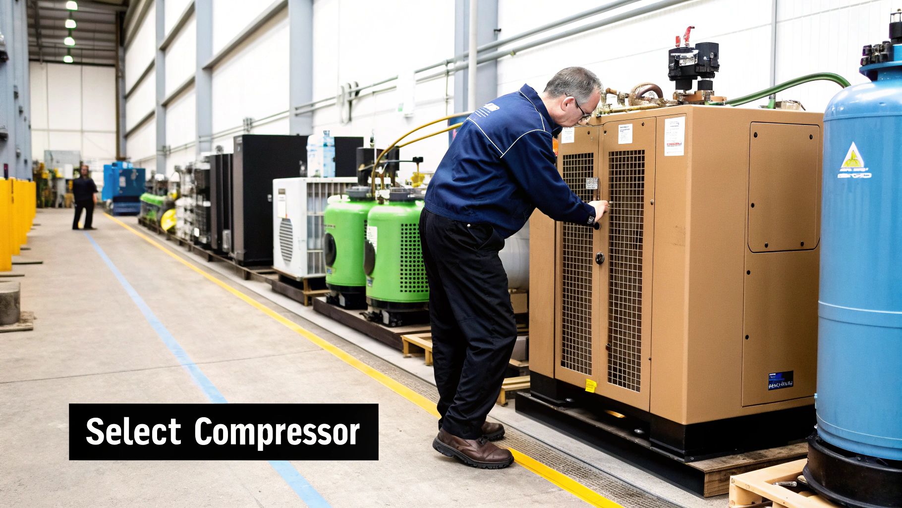
The Heart of the System: The Air Compressor
The journey of compressed air always starts at one place: the air compressor. This is the powerhouse of your whole setup. It pulls in ordinary air from the surroundings and pressurises it, storing it as potential energy ready to do work. Think of it as the lungs of the system, taking a deep breath and holding it.
Choosing the right compressor is one of the most critical decisions you'll make. Get it wrong, and you'll run into problems. An undersized compressor will constantly struggle to keep up with demand, while an oversized one is just a waste of energy and money.
The Gatekeepers: Air Preparation Units (FRLs)
Once the air is compressed, it's not quite ready for action. It's usually hot, filled with contaminants, and damp—a nasty combination that can wreak havoc on your downstream components. This is where the Air Preparation Unit, or FRL (Filter-Regulator-Lubricator), steps in. It’s the system's own quality control checkpoint.
An FRL unit is typically made of three parts:
- Filter: This is the first line of defence. It strips out solid particles like dust and rust and separates out any liquid water or oil.
- Regulator: Next up, the regulator takes control of the pressure. It makes sure the air heading into the rest of the system is at a steady, optimised pressure, ironing out any fluctuations that could cause problems.
- Lubricator: This part adds a very fine mist of oil to the air. It’s worth noting, though, that lubricators are becoming less common as many modern pneumatic parts are designed to be "lube-for-life."
A well-maintained FRL unit is non-negotiable if you want your system to last. Clean, dry, and properly regulated air is the secret to minimising wear and tear on your more expensive parts, like valves and actuators.
The Brains: Directional Control Valves
If the compressor is the heart, then directional control valves are the brains of the operation. These clever devices are responsible for sending compressed air to the right place at the right time. In short, they tell the system's "muscles" when to move, which way to go, and when to stop.
Valves are typically categorised by their ports (the pathways for air) and positions (the different states the valve can be in). For instance, a "5/2 valve" has five ports and two positions. This setup is perfect for controlling a double-acting cylinder, allowing it to move both forwards and backwards. Getting your head around these fundamentals is key, and you can explore more in our guide to pneumatic system basics.
The Muscle: Actuators and Cylinders
Finally, we get to the components that do the actual physical work: the actuators. These devices are what convert the stored energy of the compressed air into real mechanical motion. They are the muscles of your system, doing all the pushing, pulling, lifting, and turning.
The most common actuators you’ll come across are:
- Pneumatic Cylinders: These provide linear motion—movement in a straight line. They come in two main flavours: single-acting (air pushes the piston one way, a spring pushes it back) and double-acting (air pressure is used to move the piston in both directions).
- Rotary Actuators: When you need a twisting or turning motion, these are what you'll use. They create rotational force, perfect for jobs like opening and closing a valve or rotating a component.
Each part, from the compressor that creates the power to the actuator that delivers it, has an essential role. A well-designed pneumatic system is all about picking the right components and making sure they all work together seamlessly.
How to Correctly Size Your Pneumatic System
Getting the sizing right is where a good pneumatic design becomes a great one. If your system is undersized, it'll constantly struggle, leading to poor performance and components failing far too soon. On the flip side, an oversized system is a classic case of wasted energy, which directly translates to inflated running costs.
This section is your practical, hands-on guide to nailing the essential calculations that form the backbone of a properly sized system. We'll ditch the dry formulas and work through some real-world examples to build your confidence. By the end, you'll know exactly how to figure out the force your actuator needs and how to calculate the total air demand for your setup—two of the most critical steps in any design.
Calculating Required Cylinder Force
First things first, you need to answer a simple question: how much force does the actuator actually need to do its job? The core principle here is straightforward, captured by the formula F = P x A.
- F (Force): This is the output force you need from the cylinder, measured in Newtons (N).
- P (Pressure): This is your system's operating pressure, measured in Pascals (Pa) or, more commonly, bar.
- A (Area): This refers to the effective surface area of the cylinder's piston, measured in square metres (m²).
Let's make this real. Imagine you need to design a machine that lifts a 50 kg box straight up. Before anything else, we have to convert that mass (kg) into a force (N) by factoring in gravity (9.81 m/s²).
Force Calculation Example: Force (N) = Mass (kg) × Gravity (m/s²) Force (N) = 50 kg × 9.81 m/s² = 490.5 N
So, our cylinder needs to generate at least 490.5 N of force just to get the box off the ground. But in the real world, you always need a buffer. It's a solid rule of thumb to add a safety margin of around 25% to cover friction and other little inefficiencies in the system. Our new target force is 490.5 N × 1.25 = 613.1 N.
With our required force locked in, we can now work backwards to find the perfect cylinder size for our system's operating pressure. Let's assume we're working with a standard pressure of 6 bar (which is 600,000 Pa).
Piston Area Calculation Example: Area (m²) = Force (N) / Pressure (Pa) Area (m²) = 613.1 N / 600,000 Pa = 0.00102 m²
This calculation tells us we need a cylinder with a piston area of at least 0.00102 m². From here, you’d simply check manufacturer datasheets to find a standard cylinder bore size that meets or exceeds this area. It's a simple bit of maths that prevents the all-too-common mistake of picking a cylinder that’s too weak for the task.
This infographic helps visualise how crucial design parameters like operating pressure, airflow, and efficiency are all linked.
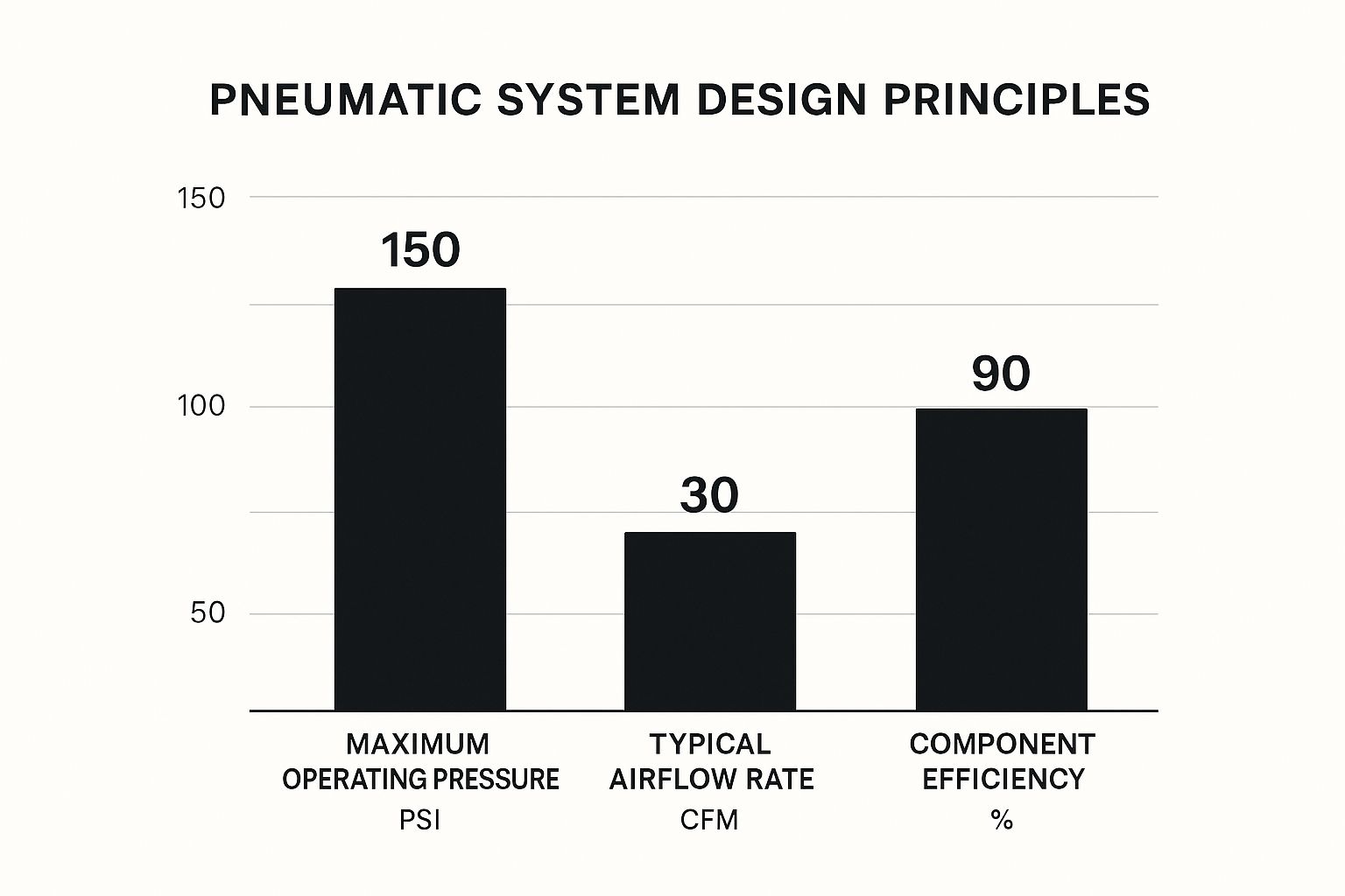
As you can see, these three factors are completely interconnected. A change in one area, like bumping up the pressure, will have a direct knock-on effect on the system's performance and how much air it consumes.
To help you get a quick feel for how cylinder size and pressure relate to force, here’s a handy reference chart.
Pneumatic Cylinder Force Chart (Newtons)
This table shows the approximate push force (in Newtons) generated by different cylinder bore sizes at various operating pressures, helping designers quickly estimate component requirements.
| Bore Size (mm) | Force at 4 bar (N) | Force at 6 bar (N) | Force at 8 bar (N) |
|---|---|---|---|
| 32 | 322 | 483 | 643 |
| 40 | 503 | 754 | 1005 |
| 50 | 785 | 1178 | 1571 |
| 63 | 1247 | 1870 | 2493 |
| 80 | 2011 | 3016 | 4021 |
| 100 | 3142 | 4712 | 6283 |
| 125 | 4909 | 7363 | 9817 |
This chart is a great starting point, but always remember to do your specific calculations and consult manufacturer data for precise figures.
Determining Total Air Consumption
Once you've figured out the sizes of your actuators, the next vital step is to calculate the total air consumption of your entire system. This number, usually given in litres per minute (l/min) or Standard Cubic Feet per Minute (SCFM), is absolutely essential for sizing your air compressor and receiver tank correctly.
To work this out, you need to find the volume of air each actuator uses per cycle, and then multiply that by how many times it cycles per minute.
For a typical double-acting cylinder, you need to account for both the extend and retract strokes:
- Calculate the volume for the extend stroke: (Piston Area) × (Stroke Length)
- Calculate the volume for the retract stroke: (Piston Area - Rod Area) × (Stroke Length)
- Add them together to get the total air volume used in one full cycle.
- Multiply by the cycles per minute to get the air consumption for that one cylinder.
You'll need to repeat this process for every single air-powered component in your system and then add all the figures together. This gives you your total air demand.
Just like with the force calculation, it’s smart to add a contingency buffer—around 20-30% is a good range. This buffer accounts for any future expansions, the tiny air leaks that inevitably develop over time, and it ensures your compressor isn’t forced to run flat-out at 100% capacity all day. Getting this number right means you’ll choose a compressor that can handle peak demand without being wastefully oversized for normal operation.
Selecting the Right Components for the Job
With the calculations out of the way, it’s time to move from theory to hardware. Choosing the right components isn't about finding the "best" part on the market; it's about finding the perfectly suited part for your specific job. This is where your design guide becomes a practical buyer's guide, ensuring what you build is not just functional, but truly optimised for its task and environment.
Getting this right means understanding the trade-offs involved. For example, does your application need the simplicity of a single-acting cylinder, or the controlled, two-way power of a double-acting one? Is linear motion what you need, or the twisting force of a rotary actuator? Nailing these initial choices is the foundation for a reliable and efficient system.
Choosing the Right Actuator for the Motion
The actuator is the real muscle of your pneumatic system, so its selection is absolutely critical. The choice you make here really boils down to the type of movement you need to achieve.
- Single-Acting Cylinders: Think of these as the sprinters of the pneumatic world. Air pressure pushes the piston out, and a simple internal spring pushes it back. They’re fantastic for quick, straightforward jobs like clamping or ejecting parts, but keep in mind their force is limited on that spring-powered return stroke.
- Double-Acting Cylinders: When you need more control and power, these are your go-to. They use air pressure for both the extend and retract strokes, giving you full force in both directions. This makes them ideal for heavier tasks like lifting, pressing, or applications requiring precise positioning.
- Rotary Actuators: If your application needs to turn, twist, or pivot, a rotary actuator is the only answer. They cleverly convert the linear force of compressed air into rotational motion, which is essential for jobs like opening and closing valves or reorienting components on an assembly line.
Decoding Directional Control Valves
Valves are the brains of the operation, directing the airflow to your actuators. Their configurations, like 3/2 or 5/2, can sound a bit technical, but they're quite simple once you crack the code. The first number tells you how many ports (air connections) it has, and the second tells you the number of positions (or states) it can be in.
A 3/2 valve has three ports and two positions. It's the standard choice for controlling a single-acting cylinder, as it expertly manages the air inlet, the outlet to the cylinder, and the exhaust. A 5/2 valve, with its five ports and two positions, is designed to control a double-acting cylinder. It has two separate ports to send air to either side of the piston, giving you that full two-way control.
Getting to grips with these configurations is a core part of any good pneumatic system design guide. For more complex systems, you'll often run into solenoid-operated valves. These use a small electrical signal to shift the valve’s position, opening the door to automated control from a PLC or computer. You can explore these in more detail in our overview of pneumatic solenoid valves.
Material and Environmental Considerations
A component’s material and its ability to survive its environment are just as crucial as its performance specs. If you overlook these details, you’re setting yourself up for premature failure and expensive downtime.
Material Selection: The material has to match the working environment. For example:
- Stainless Steel: This is the default choice for food processing, pharmaceutical, or any washdown environment. Its hygiene properties and fantastic corrosion resistance are second to none.
- Aluminium: A versatile and lightweight option, it's perfect for general industrial automation where extreme corrosion isn't a primary concern.
- Plastics/Polymers: These are often used for fittings or in applications where weight is a critical factor and resistance to specific chemicals is required.
Environmental Protection (IP Ratings): Any component used in dusty, wet, or otherwise harsh conditions needs to have an appropriate Ingress Protection (IP) rating. An IP rating, such as IP65, tells you exactly how well the part is sealed against solids (the first digit) and liquids (the second digit). A valve rated at IP65 is completely dust-tight and protected against water jets, making it more than suitable for most challenging factory floors.
How to Read and Create Pneumatic Schematics
Think of a pneumatic schematic as the system's road map. It’s not just a technical drawing; it’s a universal language that shows every connection, every component, and exactly how air will flow through the circuit. Getting comfortable with these diagrams is one of the most crucial skills you can develop, as it lets you design, build, and troubleshoot any pneumatic system with confidence.
Before you even think about connecting a single hose, a good schematic lets you trace the entire operational logic. This is where you catch potential problems and refine the sequence of operations, saving a huge amount of time, money, and frustration down the line.
The Language of Pneumatics: ISO 1219 Symbols
To get fluent in schematics, you first need to learn the alphabet. In the world of pneumatics, this means getting to grips with the symbols standardised under ISO 1219. This standard is incredibly important—it means a diagram drawn up by an engineer in the UK can be perfectly understood by a technician in Germany or Japan, without any confusion.
You'll quickly start to recognise the most common symbols. Here are a few to get you started:
- Air Source: The starting point of it all. A simple circle represents the compressor or pressure source that supplies the system.
- Actuators: Cylinders are usually shown as rectangles with a line for the piston and rod. You can immediately tell if it’s single-acting (look for the zigzag line indicating a spring return) or double-acting.
- Valves: These are drawn as boxes. Each box represents a different "position" the valve can be in, and the arrows inside show the air's path for that position.
- FRL Unit: This is often shown as a simplified diamond shape, sometimes with a dotted line connecting it to other symbols, representing the filter, regulator, and lubricator that condition the air.
Key Insight: Don't feel you need to memorise every symbol overnight. Just focus on the fundamentals first: compressors, valves, and cylinders. As you work with more complex circuits, you can look up new symbols and your visual vocabulary will grow naturally.
From Simple Circuits to Complex Sequences
The best way to learn is by doing. Let's walk through a very common, basic circuit: using a 3/2 push-button valve to control a single-acting cylinder.
- First, you'd draw the air source connecting to port 1 of the 3/2 valve.
- Next, port 2 of the valve connects to the single port on the cylinder.
- Finally, port 3 is the exhaust, which is often shown with a small triangle symbol.
When you trace the logic, it becomes clear. Pressing the button shifts the valve, letting air flow from port 1 to port 2 and extending the cylinder. Let go, and the valve's internal spring snaps it back. This new position connects port 2 to the exhaust port 3, venting the air and allowing the cylinder's own spring to retract the piston. It’s that simple.
Once you understand this basic principle, building more advanced schematics is just a matter of adding more layers. For instance, creating a sequencing circuit where one cylinder extends and then triggers a second one is just an expansion of this logic. You'd simply add another cylinder and valve, using something like a limit switch on the first cylinder to activate the valve for the second. This is why schematics are so powerful—they ensure your design is logical, efficient, and easy for anyone to build and maintain.
Essential Maintenance and Troubleshooting Tips

Any pneumatic system is only as good as the care you put into it. Getting ahead with proactive maintenance is always better than scrambling to fix a breakdown, saving you from costly downtime and keeping your whole operation running safely and smoothly. This part of our pneumatic system design guide is all about the practical, hands-on steps you can take to keep your equipment in prime condition.
Think of it like owning a car. You wouldn't skip an oil change, would you? Your pneumatic system needs the same kind of routine attention to stop tiny issues from snowballing into catastrophic failures. A straightforward maintenance plan is your best line of defence.
Key Takeaway: The single most common—and expensive—problem you'll face is an air leak. Just one 1.5 mm leak at 6 bar of pressure can waste over £500 a year in energy. That makes finding and fixing leaks your number one job.
Building a Proactive Maintenance Checklist
A consistent maintenance schedule is easy to put in place and pays for itself in reliability. By focusing on these core tasks, you can squeeze more life out of your components and keep performance exactly where it needs to be.
Your routine checks should cover:
- Draining FRL Bowls: Water is the arch-nemesis of any pneumatic component. Get into the habit of regularly draining the filter bowl on your Air Preparation Unit (FRL). This removes collected moisture and gunk before it can cause damage downstream.
- Checking Pressure Settings: Make sure your system's operating pressure is where it should be according to your design specs. The wrong pressure leads to sluggish performance at best and excessive wear and tear at worst.
- Inspecting Tubing and Hoses: Give all your lines a quick visual check. Look for any signs of cracking, rubbing, or kinking. A damaged hose is a frequent point of failure, but it’s also one of the easiest to spot and replace.
- Listening for Leaks: Simply walk the line and listen. The distinct hissing of an air leak is hard to miss, especially around fittings and connections. If you think you hear something, a quick spray of a soap-and-water solution on the joint will confirm it with bubbles.
A Practical Troubleshooting Guide
Even with the best maintenance plan, things can still go wrong. When they do, a logical step-by-step approach will help you pinpoint the root cause without wasting time. This guide connects common symptoms to their most likely culprits.
Common Problems and Likely Causes
Problem: Cylinder action is slow or sluggish.
- Low Pressure: The first thing to check is your regulator. Is it set correctly?
- Air Leak: The cylinder itself or the valve feeding it could be losing air.
- Flow Control Restriction: Your flow control valve might be dialled in too tightly, choking the airflow.
- Clogged Silencer: A blocked exhaust silencer can trap air on the way out, which really slows down the retract stroke.
Problem: The compressor runs constantly.
- Significant Air Leak: You’ve got a major leak somewhere. The compressor is working overtime just to keep up.
- Increased Demand: Has new equipment been added recently? You might have exceeded the system's original air demand calculations.
- Faulty Pressure Switch: The switch that signals the compressor to turn on and off could have given up the ghost.
Problem: Actuator timing is off or inconsistent.
- Valve Issue: The solenoid on the control valve might be getting sticky or is on its way out.
- Control Signal: In automated setups, the signal from the PLC might be dropping out. You can learn more about how timing is managed by exploring different pneumatic timers and what they do.
By following this simple maintenance checklist and using this troubleshooting guide, you can ensure your pneumatic system remains a dependable and productive workhorse for years to come.
Your Pneumatic Design Questions, Answered
Even the best-laid plans run into questions. It’s just part of the design process. This section of our guide is dedicated to tackling the most common queries we hear from designers out in the field. We’ll give you clear, straightforward answers to help you get past those common hurdles and make confident decisions.
Whether you're trying to squeeze more efficiency out of your system or stuck choosing between two components, these insights are drawn from real-world experience. We're here to break down the tricky topics into simple, practical advice that works for everyone, from newcomers to seasoned pros.
How Can I Make My Pneumatic System More Energy-Efficient?
Boosting your system's energy efficiency is often simpler than you might think, and it nearly always starts by eliminating waste. The undisputed number one source of wasted energy in any pneumatic setup is air leaks. A regular check of all your fittings, seals, and tubing with an ultrasonic leak detector—or even just a simple soap-and-water solution—will help you find and fix them fast.
Next, have a look at your operating pressure. You should always aim to run your system at the lowest possible pressure that still gets the job done reliably. Anything more is just wasted energy.
As a rule of thumb, for every 2 PSI (that's about 0.14 bar) you lower your system's pressure, you can cut your energy bill by roughly 1%. It might not sound like much, but those small adjustments really add up over time.
Finally, make sure your components are properly sized for the application. An oversized cylinder, for instance, gulps down more compressed air than it needs with every single stroke, which directly drives up your energy use. Getting the sizing right is a fundamental part of any efficient design.
What’s the Difference Between a 3/2 and a 5/2 Valve?
Those numbers on a valve can look a bit technical, but they’re actually a simple shorthand for what the valve does. They tell you the number of ports and the number of positions, which is crucial for matching the right valve to your actuator.
- A 3/2 Valve: This valve has 3 ports and 2 positions. It’s the go-to choice for controlling a single-acting cylinder (the kind with a spring return). Its ports are set up to handle the air inlet, the outlet going to the cylinder, and the exhaust.
- A 5/2 Valve: This one has 5 ports and 2 positions. It's the standard for controlling a double-acting cylinder because it has to send air to both sides of the piston to extend and retract it. It features one air inlet, two outlets (one for each side of the cylinder), and two matching exhaust ports.
When Should I Use a Lubricator in My System?
The short answer? Only when a component’s manufacturer specifically tells you to. The vast majority of modern pneumatic parts, including most cylinders and valves, are designed to be 'lube-for-life'. Adding oil to a system that uses these components can actually do more harm than good, as it can wash away the special factory-applied grease and lead to premature failure.
If you do have a specific piece of equipment that requires lubrication—like certain air motors or some older-style cylinders—the best practice is to install a point-of-use lubricator right before that device. This approach prevents unwanted oil mist from spreading through and contaminating the rest of your system. When in doubt, always check the manufacturer's datasheet first.
For all your component needs, from control valves to actuators and FRLs, explore the extensive range at Solenoid Valve World. Find the right parts for your system today by visiting https://solenoid-valve.world.