Pressure Reducing Valves for Air and Water: Expert Guide
Understanding What Makes Pressure Reducing Valves Essential
In any system designed to move fluids, from compressed air on a factory floor to water in a municipal network, pressure is a critical factor. While essential for operation, uncontrolled or fluctuating pressure can cause significant problems, ranging from slow component wear to sudden, catastrophic system failure. This is where pressure reducing valves (PRVs) become indispensable. They act as automatic regulators, sensing and adjusting to maintain a steady, safe downstream pressure, no matter how high or unpredictable the upstream pressure gets. This stabilising action is vital for protecting downstream equipment, maintaining process consistency, and avoiding expensive damage.
Why Stable Pressure Is Non-Negotiable
Consider a pneumatic production line where sensitive tools need a precise air pressure of 6 bar to function correctly. If the main compressor line fluctuates between 8 and 10 bar, these tools will wear out prematurely, causing unplanned downtime and costly repairs. Likewise, in a home water system, high mains pressure can damage appliances like washing machines and water heaters, not to mention increasing water waste. In these situations, a pressure reducing valve for air and water acts as a silent guardian, ensuring the output pressure is always predictable, even when the input is not.
The diagram above illustrates the core principle of a direct-acting PRV. A spring and diaphragm assembly work in opposition to the downstream pressure. When downstream pressure climbs above the set point, it forces the diaphragm upwards, which closes the valve and restricts the flow until the target pressure is achieved again. This simple mechanical feedback loop is the foundation of how these devices protect your systems.
From Theory to Practical Application
The difference between PRV types, such as direct-acting and pilot-operated, isn't just a technical detail—it has direct implications in the field. A direct-acting valve, with its simple spring-and-diaphragm design, is often the best fit for smaller-scale systems or where a quick response to flow changes is required.
However, for larger systems that demand greater accuracy and stability under varying flow conditions, a pilot-operated valve is the superior option. Its more advanced design uses the system's own pressure to help control the main valve, allowing for much finer regulation. The importance of these devices is clear from their widespread use. You can explore the different technologies in action by looking through our complete range of pressure reducing valves.
Globally, the market accounts for around 25 million PRV units sold each year, a figure that highlights their critical role across industries. This demand is boosted by regional initiatives, such as those in the UK focused on improving water network efficiency and reducing leaks. You can learn more about the global PRV market and its key drivers by exploring the full market analysis from IMARC Group.
Air vs Water PRVs: Why Your Medium Choice Changes Everything
A common and costly mistake is to assume pressure reducing valves for air and water are interchangeable. While they perform the same fundamental task, the physical properties of the fluid—a compressible gas versus an incompressible liquid—demand fundamentally different design approaches. Choosing the wrong type won't just lead to poor performance; it can cause system damage, operational instability, and serious safety hazards. The differences are not just about material choice but are rooted in fluid dynamics.
This cutaway shows the internal mechanics common to many industrial pressure reducing valves, highlighting the diaphragm and spring that work together to regulate pressure.
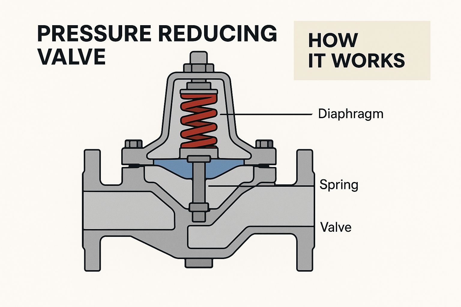
Understanding this core mechanism is the first step in appreciating why the medium being controlled is so critical to the valve's internal design and performance.
The Compressibility Factor: Air Systems
Air, being a compressible gas, has the ability to store energy. When an air PRV opens, the downstream volume fills very quickly, and the pressure can overshoot the set point. If the valve closes too rapidly in response, the pressure plummets, prompting it to open again. This cycle, known as pressure hunting, creates damaging oscillations throughout the system.
To counteract this, PRVs designed for air often have specific features:
- Damping Mechanisms: These might be smaller internal orifices or dashpots that deliberately slow the valve's response time, preventing the rapid cycling that causes instability.
- Balanced Poppet Design: Many air PRVs employ a balanced poppet, where upstream pressure acts on both sides of the valve plug. This design minimises the impact of upstream pressure fluctuations on the set point, delivering much greater stability.
- Material Selection: While both air and water can be corrosive, compressed air often contains oil and moisture. This requires seals and diaphragms made from materials like Nitrile (Buna-N) or FKM, which resist degradation from these specific contaminants.
The Incompressibility Factor: Water Systems
Water, as an incompressible liquid, introduces an entirely different set of challenges. The main concern in water applications is cavitation. This destructive process happens when the liquid's pressure drops below its vapour pressure as it squeezes through the valve's restricted opening, forming vapour bubbles. As these bubbles flow downstream into a higher-pressure zone, they collapse violently. This collapse generates tiny, high-energy shockwaves that can erode valve internals and downstream piping, creating significant noise and causing premature failure.
PRVs for water are engineered specifically to fight this destructive force:
- Hardened Trim Materials: Valve seats and plugs are frequently made from hardened materials like stainless steel to endure the erosive impact of cavitation. Bronze and brass are common body materials due to their excellent corrosion resistance in water.
- Specialised Trim Designs: Some water PRVs have multi-stage or cage-style trims. These designs break the total pressure drop into several smaller, more manageable steps. This keeps the fluid pressure above its vapour point, preventing cavitation from starting in the first place.
- Flow Path Optimisation: The internal shape of the valve is designed to be as smooth as possible. This minimises the sharp turns and sudden restrictions that create low-pressure zones and encourage bubble formation.
To make the right choice, it's vital to understand how these design requirements differ at a component level. The following table breaks down the critical differences between air and water PRVs.
Air vs Water PRV Critical Design Differences
Essential comparison of design elements that determine success or failure in air versus water applications
| Design Element | Air PRV Requirements | Water PRV Requirements | Why This Matters |
|---|---|---|---|
| Response Speed | Slower, damped response to prevent "hunting" and pressure oscillations. | Faster response to manage immediate pressure changes. | Mismatched response causes instability in air systems and potential pressure spikes in water systems. |
| Primary Failure Concern | System instability and seal degradation from oil/moisture. | Physical erosion and damage from cavitation. | The design focus is entirely different: stability for air versus durability against physical forces for water. |
| Internal Trim Design | Often uses a balanced poppet to negate upstream pressure fluctuations. | May use multi-stage or cage-style trims to manage pressure drops in steps, preventing cavitation. | A simple poppet in a high-pressure drop water application will be quickly destroyed by cavitation. |
| Seal & Diaphragm Material | Nitrile (Buna-N) or FKM to resist oil and moisture carry-over. | EPDM or other materials suitable for potable water and chlorine. | Using the wrong seal material leads to rapid failure, leaks, and system contamination. |
| Body & Trim Materials | Cast iron or aluminium for the body; brass or stainless steel for trim. | Bronze, brass, or stainless steel bodies for corrosion resistance; hardened stainless steel trim to resist erosion. | An air PRV's materials may not withstand the constant corrosive and erosive effects of a water system. |
This comparison shows that while both are "pressure reducing valves," their internal engineering is tailored to opposing physical principles. Using an air PRV for water risks rapid failure from cavitation, while using a water PRV for air can lead to an unstable, oscillating system that is impossible to control precisely.
Choosing the Right Valve Technology for Your Situation
 Choosing the correct pressure reducing valves for air and water goes beyond simply matching pipe sizes. It demands a pragmatic look at the valve's core technology versus your system's real-world needs. While marketing often promotes the most advanced features, a simpler, more robust design can frequently offer better reliability than a complex alternative. The goal is to recognise the operational trade-offs between different designs.
This means looking past basic specifications to see how each valve type performs under specific operational pressures. A straightforward direct-acting valve may be perfectly suited for a low-flow application, but a pilot-operated model is necessary for maintaining tight pressure control in a system with high flow rates and large pressure drops.
Direct-Acting vs. Pilot-Operated: A Practical Comparison
The most frequent decision for engineers and maintenance teams is between direct-acting and pilot-operated valves. This choice fundamentally affects the valve's accuracy, response speed, and suitability for different system sizes.
Direct-Acting Valves: These are the dependable workhorses of pressure regulation. Their uncomplicated design features a spring that directly counters the downstream pressure acting on a diaphragm. This setup provides a swift response to flow changes, making them an excellent choice for smaller, point-of-use scenarios like regulating air to a single pneumatic tool or safeguarding a specific piece of machinery. Their primary limitation is droop, where outlet pressure falls slightly as flow increases. For applications where a 5-10% pressure fluctuation is acceptable, their simplicity is a major benefit.
Pilot-Operated Valves: For larger systems that demand high flow capacity and superior accuracy, pilot-operated valves are the clear choice. They employ a small internal pilot to manage the main valve's opening, using the system's own pressure to perform the regulation. This design delivers far more stable downstream pressure, often with less than 1% deviation from the set point, even with significant flow variations. This level of precision is essential in municipal water networks or large-scale industrial air systems where consistency is non-negotiable.
To help cut through marketing claims and focus on practical performance, the following table compares these technologies based on real-world operational realities.
PRV Technology Reality Check Matrix
Honest comparison of valve technologies showing real-world performance versus marketing claims
| Technology | Actual Response Time | Real-World Accuracy | True Maintenance Needs | Best Fit Applications |
|---|---|---|---|---|
| Direct-Acting | Very fast (milliseconds) | Moderate (5-10% droop is common) | Low; simple to troubleshoot and replace seals or diaphragms. | Point-of-use air regulation, protecting individual equipment, low-flow water lines. |
| Pilot-Operated | Slower (seconds) | High (typically <1% pressure deviation) | More complex; requires clean media and periodic checks of pilot orifices. | Main water distribution lines, large-scale plant air systems, high-capacity process lines. |
| Dome-Loaded | Fast to moderate | Extremely high (often <0.5% deviation) | Low, but requires a clean, stable gas source for the dome. | High-stakes test benches, critical process control, applications where spring fatigue is a risk. |
The key takeaway is that the 'best' valve is the one whose performance characteristics align with the system's tolerance for pressure variance and flow demand. Over-specifying can lead to unnecessary cost and complexity.
Specialised and Emerging Technologies
Beyond the two main types, other designs address unique challenges. Dome-loaded pressure regulators, for example, use a trapped gas pressure (the "dome") instead of a mechanical spring as a reference force. This design enables exceptionally precise and repeatable pressure control, making it ideal for high-stakes testing or process control where spring fatigue could compromise results.
The UK's emphasis on infrastructure upgrades and energy efficiency is also driving manufacturers toward more advanced designs. British companies are at the forefront, with new pressure reducing valve series launched in late 2024 aimed at cutting energy use and simplifying maintenance. You can read more about the factors influencing these trends in this detailed analysis of the pressure reducing valve market.
For integrated systems, it's also useful to understand how PRVs function alongside other components. In many automated processes, they work with solenoid valves for precise fluid management. Our guide on pneumatic solenoid valves offers more detail on how these components can be effectively combined. Matching the valve technology to your operational reality ensures you get dependable performance without paying for features you don't need.
Selecting Valves That Actually Work in Your System
 Standard selection charts often don't account for the real-world conditions that determine a valve's true performance. Choosing pressure reducing valves for air and water that will operate reliably for years means looking beyond the basic specifications to consider the full operational picture. Factors like flow variations, temperature changes, and environmental conditions are what separate a dependable workhorse from a persistent maintenance issue.
A practical selection process starts by properly assessing your system's demands. This step often shows that common assumptions can be misleading. For example, one of the most frequent and damaging errors is oversizing a valve.
The Problem with Oversizing and Flow Estimation
It might seem sensible to select a valve with extra capacity, but an oversized PRV often causes more problems than one that's slightly undersized. When a valve is too large for the actual flow rate, it spends most of its time operating very close to its seat. This tiny opening forces the fluid through at a very high velocity, which leads to several issues:
- Wire drawing: The high-speed flow erodes the seat and plug, similar to a wire being pulled through a die. This causes permanent damage, leading to leaks and eventual failure.
- Instability: At such low flow rates, the valve struggles to hold a steady downstream pressure, causing pressure fluctuations and "hunting" as it tries to find a stable position.
- Noise and vibration: The turbulent flow generates considerable noise and can create vibrations that affect the entire system.
The correct approach is to size the valve for the actual flow conditions, not the theoretical maximum capacity of the pipework. A valve performs best when operating between 25% and 75% of its capacity, as this range allows for effective pressure regulation. Accurately measuring or calculating both minimum and maximum flow rates is crucial for making the right choice.
Beyond the Datasheet: Environmental and Lifecycle Factors
A valve’s true value extends far beyond its initial purchase price. The total cost of ownership must account for installation, energy use, maintenance, and the cost of any potential downtime. A cheaper valve might look appealing initially but can introduce significant hidden costs down the line.
Consider material selection in different environments. For a typical water application, a bronze body might be perfectly adequate. However, if the water has a high chloride content or the valve is installed in a chemical processing plant, stainless steel or other specialised alloys are needed to prevent rapid corrosion. Likewise, in compressed air systems where compressor oils are present, seals made from materials like FKM are required instead of standard EPDM.
Maintenance access is another vital but frequently ignored consideration. A valve installed in a cramped, difficult-to-reach location will likely have its routine inspections postponed, which can lead to preventable failures. Planning for easy access to adjustment screws, diaphragms, and pilot filters during the initial design stage saves a great deal of time and money over the valve's working life. The key to choosing a valve that genuinely works is balancing the initial investment against these long-term operational needs.
Installation Strategies That Prevent Future Problems
Most premature failures of pressure reducing valves for air and water don't stem from manufacturing defects. Instead, they are often the result of installation errors that create problems months or even years down the line. By concentrating on a few critical installation steps, technicians can prevent common issues, ensuring long-term reliability and avoiding expensive corrective work. A proactive installation approach involves understanding how piping, valve orientation, and commissioning directly influence a PRV’s lifespan and performance.
The Importance of Upstream and Downstream Piping
The pipework immediately surrounding a pressure reducing valve has a profound impact on its operation. A frequent mistake is failing to provide straight pipe runs both upstream and downstream of the valve. Field experience consistently shows that placing elbows, tees, or other fittings too close to the PRV generates turbulence. This unsettled flow can cause the valve’s internal components to “hunt” for a stable position, leading to pressure fluctuations and accelerated wear on the diaphragm and seat.
As a best practice, install a straight pipe run of at least 5 to 10 times the pipe diameter before and after the valve. This simple measure allows the flow to stabilise, giving the valve a consistent pressure signal and helping it regulate accurately. This setup is especially important for pilot-operated valves, which are more sensitive to turbulent conditions.
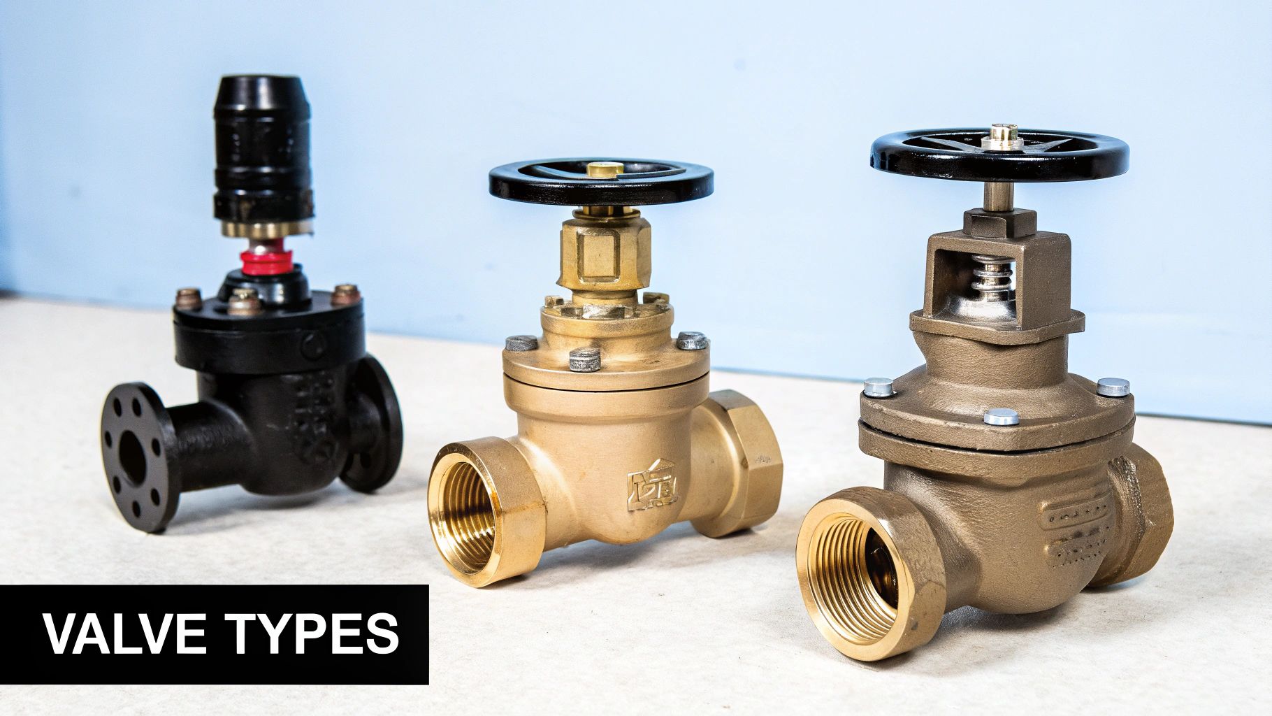
This image shows a variety of pressure regulators, highlighting the different sizes and configurations used across industries. The variety proves there is no one-size-fits-all solution; correct installation is essential for any of these designs to work effectively within a specific system.
Filtration and Orientation: Non-Negotiable Details
Debris is another common cause of failure. Small particles of rust, scale, or sealant from the pipework can easily become lodged in the valve’s seat or block the small sensing ports in pilot-operated models. To avoid this, always install a strainer or filter upstream of the PRV. This is a small investment that protects a much more critical component. A strainer with a 100-mesh screen is typically sufficient for most air and water applications.
Valve orientation also matters more than many technicians realise. Most pressure reducing valves are designed for installation on horizontal pipe runs with the adjustment spring pointing upwards. Installing a valve upside down or vertically can interfere with the diaphragm's movement and affect the accuracy of the spring mechanism, leading to poor pressure control. Always check the manufacturer's installation manual to confirm the correct orientation for your specific model. By addressing these foundational details—proper piping, filtration, and orientation—during the initial setup, you create the foundation for a stable and reliable pressure management system.
Maintenance Approaches That Actually Extend Valve Life
Relying on a generic, time-based maintenance schedule for **pressure reducing valves for air and water** can be inefficient. This approach often results in unnecessary downtime and misses the early warning signs of failure. Instead, a more practical method is **condition-based maintenance**, which involves observing specific symptoms that signal a developing problem. This strategy allows you to address minor issues affordably before they become major system failures.Making the switch from reactive repairs to a predictive strategy starts with knowing what to look for. Rather than replacing parts on a rigid calendar, maintenance teams should learn to spot genuine red flags. For example, a minor, infrequent weep from a valve might be simple condensation. However, a constant drip from the vent hole is a clear sign of a failing diaphragm, requiring immediate attention as it shows a breach between the system fluid and the control mechanism. This change in approach—from "replace every two years" to "inspect for specific symptoms quarterly"—saves both time and resources.
Real-World Diagnostic Techniques
You don't need sophisticated equipment to start using this method. Simple, hands-on checks can offer valuable information. One effective technique is to listen to the valve as it operates. If the valve "hunts" or chatters with a noticeable metallic sound, it often indicates instability from being oversized for the application or from turbulent flow, not necessarily a fault with the valve itself.
Another important diagnostic is to regularly check the downstream pressure using a calibrated gauge. If the pressure gradually increases when the system has no flow, it points directly to a worn or debris-fouled seat. This is a common issue that is relatively straightforward to fix if identified early.
The true source of a failure is often within the system, not the valve alone. In fact, an estimated 90% of valve failures are caused by external factors such as dirt, debris, or incorrect installation. Debris is the most frequent culprit, which highlights the importance of proper upstream filtration.
By examining a failed component, you can diagnose the root cause. A heavily eroded seat on a water valve suggests cavitation, meaning the pressure drop is too high for that specific valve model. In a pneumatic system, a sticky or degraded diaphragm often points to oil contamination from the compressor. Identifying these failure modes helps you fix the underlying issue, like improving filtration or air quality, rather than just repeatedly replacing the valve. As you refine your maintenance plans, you might find our guide on selecting a water flow control valve useful for related systems. This proactive, symptom-driven approach helps your pressure reducing valves operate reliably for their entire expected service life.
Solving Real Pressure Control Problems
When a pressure control system starts acting up, it’s easy to point the finger at the valve. However, technicians with experience in pressure reducing valves for air and water understand that the problem often lies beyond the component itself. The real issue is frequently found in how the valve interacts with the wider system. A structured diagnostic approach is crucial to determine if you're dealing with a faulty valve, a system-induced problem, or an operational change that's affecting performance.
The first step is to correctly identify the symptoms. Terms like pressure hunting and control instability are not interchangeable; they signal very different root causes.
Case Study 1: Pressure Hunting in a Pneumatic System
Symptom: A workshop installed a new pneumatic line to run several assembly tools. The direct-acting PRV was cycling constantly, causing the downstream pressure to swing between 5.5 and 6.5 bar, despite a target of 6 bar. This "hunting" resulted in poor and inconsistent tool performance.
Initial Diagnosis: Believing the PRV was faulty, the maintenance team replaced it. The problem didn't go away.
Systematic Investigation:
- Upstream Analysis: An inspection of the main compressor line showed it was stable, which ruled out any issues with input fluctuations.
- Downstream Analysis: The team soon realised that the total air consumption from the new tools was surprisingly low. The PRV had been selected based on the pipe's maximum potential flow and was therefore massively oversized for the actual demand.
- Root Cause Identification: Because the valve was oversized, it was operating too close to its seat. Any small change in demand forced it to overcorrect, triggering the hunting cycle. This was a classic system design issue, not a component fault.
Solution: The oversized PRV was swapped for a smaller, correctly sized model that could operate within its ideal 25-75% flow range. This simple change immediately stabilised the downstream pressure and solved the performance issues.
Case Study 2: Gradual Pressure Creep in a Water System
Symptom: A facilities manager observed that the pressure in a commercial building's secondary water circuit was slowly climbing overnight. By morning, it was high enough to trip a safety relief valve. During the day, the pressure remained stable.
Initial Diagnosis: The immediate assumption was that the PRV was leaking internally, allowing the high mains pressure to "creep" into the secondary circuit.
Systematic Investigation:
- Upstream Analysis: The mains pressure was confirmed to be high but steady.
- Downstream Analysis: The team found a check valve installed just after the PRV to prevent backflow. They also noted a water heater was part of this same circuit.
- Root Cause Identification: The PRV wasn't leaking. During the night, when no one was using water, the heater would cycle on. The resulting thermal expansion of the water trapped in the closed loop between the check valve and the PRV had nowhere to go, causing the pressure to build. It's estimated that system factors like this account for up to 90% of what are perceived to be valve failures.
Solution: A small thermal expansion tank was fitted on the downstream side of the PRV. This gave the expanded water volume a place to go, completely resolving the pressure creep without any need to touch the valve.
These real-world examples show that effective troubleshooting demands a view of the entire system. Before replacing a valve, always investigate system interactions, operational changes, and environmental factors first.
For expert help in choosing the right valve or diagnosing complex system issues, explore the extensive range and UK-based technical support available at Solenoid Valve World.