A Guide to Solenoid Valve Control Systems
Ever needed to start or stop the flow of a liquid or gas in an instant, with absolute precision, thousands of times a day? That’s exactly the job solenoid valve control was designed for. It’s the intelligent ‘switch’ at the very heart of modern automation, telling a valve exactly when to open, when to close, and how to react with electronic accuracy.
Why Solenoid Valve Control Is So Important
In simple terms, you can think of a solenoid valve as a super-fast, remote-controlled tap. But instead of your hand turning a handle, a precise electrical signal gets the job done in milliseconds. This isn't just a matter of convenience; it’s the engine that drives efficiency, safety, and automation across countless industries, from busy manufacturing lines to critical medical equipment.
Getting the control right is what separates a chaotic, unpredictable process from a finely tuned operation. It ensures the correct amount of fluid is dispensed at the right moment, every single time. This level of precision is fundamental for consistent product quality, minimising waste, and protecting both equipment and personnel. Without it, processes would be sloppy, inefficient, and potentially dangerous.
The Foundation of Modern Automation
The applications are everywhere you look. In an automated car wash, solenoid valve control is what manages the precise sequence of water, soap, and wax. In a complex chemical plant, it doses ingredients with unwavering accuracy. Even the coffee machine on your counter and the dishwasher in your kitchen rely on these systems to manage water flow and run their cycles perfectly.
This widespread use is fuelling major market growth. For instance, the UK solenoid valve industry is projected to expand at a compound annual growth rate (CAGR) of 4.3% between 2025 and 2035. This growth is largely driven by the UK’s focus on sustainability and energy efficiency, especially in sectors like water treatment, which are adapting to government initiatives for better water quality. You can dive deeper into these trends in this detailed report from Future Market Insights.
A solenoid valve without a control system is like a light switch with no wires. It has potential, but it can't do its job until it gets a clear command.
Before we dive in, let's lay out a quick roadmap of the core concepts we'll be exploring. This table will give you a bird's-eye view of how all the pieces fit together.
Core Concepts of Solenoid Valve Control
| Concept | What It Means | Why It Matters |
|---|---|---|
| Solenoid Actuation | Using an electromagnetic coil to physically move a valve plunger or pilot. | It’s the fundamental principle that allows for fast, automated, electrical control. |
| Operating Principle | How the valve opens/closes, either directly (direct-acting) or with system pressure (pilot-operated). | Determines the valve’s suitability for different pressures, flow rates, and power needs. |
| Control Interface | The electrical or pneumatic signal that tells the solenoid what to do (e.g., 24V DC, PLC). | This is the communication link between your control system and the valve itself. |
| System Integration | Connecting the valve and its control into a larger automated system or process. | Ensures the valve works in harmony with other components to achieve a process goal. |
Understanding these building blocks is key to mastering solenoid valve control.
This guide will walk you through everything, starting with the basic mechanics of how these valves work and moving all the way to advanced system integration. We’ll cover what every engineer, technician, or manager needs to know—from choosing the right valve for the job to troubleshooting common issues in the field. By the end, you won't just know what solenoid valve control is, but how to apply it effectively in the real world.
Understanding How a Solenoid Valve Works
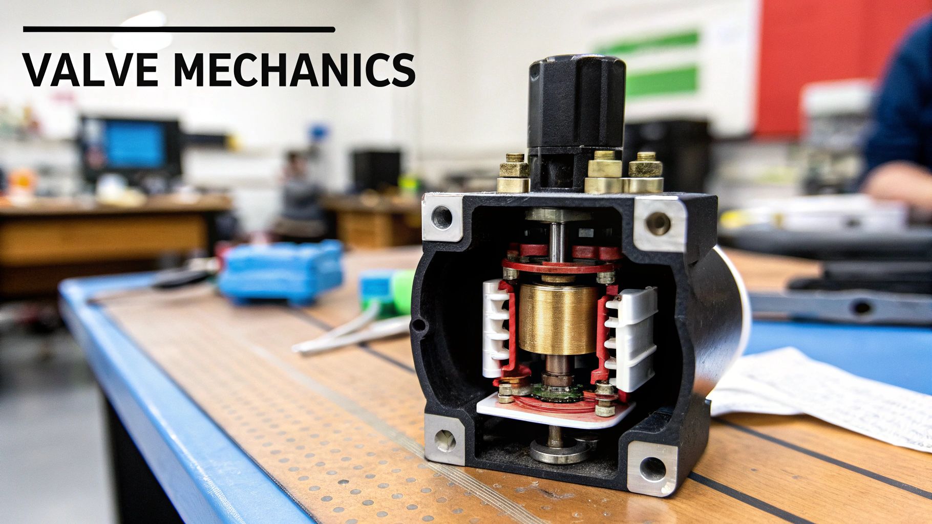
To really get to grips with solenoid valve control, we first need to pop the bonnet and see what makes the thing tick. At its heart, a solenoid valve is a clever but simple device that turns electrical energy into physical movement. It all comes down to the fundamental principle of electromagnetism.
Think about a standard magnet. You know it can pull certain metals towards it without any physical contact. A solenoid valve operates on a very similar principle, but with one crucial twist: it's a magnet you can switch on and off at will.
This on-demand magnetism is the secret to its precise operation. The entire mechanism is surprisingly straightforward, relying on just three core components working together.
The Essential Trio of Components
Every standard solenoid valve is built around three critical parts. Once you understand the role of each, the whole process becomes much clearer.
- The Solenoid Coil: This is simply a length of copper wire wrapped tightly around a hollow centre. When you pass an electric current through this wire, it generates a strong, localised magnetic field. This is the "electro" part of the electromagnet.
- The Plunger (or Armature): Inside the coil’s hollow core sits a small, moveable piston made from a magnetic metal like iron. It’s this part that gets pulled around by the magnetic field generated by the coil.
- The Valve Body: This is the main housing that contains the plunger, the coil, and the pipework for the fluid or gas. It has an inlet and an outlet port, plus a small opening called an orifice that the plunger is designed to block or unblock.
When the coil gets power, its magnetic field instantly pulls the plunger, shifting its position. This tiny movement is what opens or closes the orifice, controlling the flow. Cut the power, and the magnetic field collapses. A small spring then pushes the plunger straight back to where it started, reversing the action. It's an elegant, simple, and incredibly quick process.
You can think of the coil and plunger as a gatekeeper with an instant, remote-controlled key. The electrical signal is the command, and the magnetic field is the force that immediately unlocks or locks the gate (the orifice) to control whatever is flowing through.
Normally Open vs Normally Closed Designs
Solenoid valves are designed with a specific default state—that is, the position they adopt when no electrical power is applied. This "normal" state is a crucial safety and design feature. The two main types are Normally Closed and Normally Open.
Choosing the right one is fundamental to proper solenoid valve control. It all hinges on your application's requirements, especially what needs to happen if the power fails.
Normally Closed (NC) Valves
A Normally Closed valve is, as the name suggests, shut by default. The plunger, usually with a bit of help from a spring, rests firmly against the valve's orifice, blocking any flow.
- When Energised: The electromagnetic force lifts the plunger, opening the orifice and letting the fluid or gas pass through.
- When De-energised: The magnetic field vanishes, and the spring pushes the plunger back down, sealing the orifice and stopping the flow.
- Common Use Case: Your domestic washing machine is a perfect example. You only want water filling the drum at certain points in the wash cycle. An NC valve makes sure that if the power cuts out, the valve shuts and you don't end up with a flooded kitchen. This fail-safe design makes it the most common choice for everything from irrigation systems to coffee machines.
Normally Open (NO) Valves
On the flip side, a Normally Open valve allows flow by default. In its resting state, the plunger is held away from the orifice, allowing fluid to pass through continuously when the valve has no power.
- When Energised: The magnetic field pulls the plunger down to seal the orifice, which stops the flow.
- When De-energised: The valve pops back to its open state, and the flow resumes.
- Common Use Case: Imagine a system that needs constant ventilation, or a cooling circuit that must always have fluid circulating to prevent a machine from overheating. An NO valve ensures that if power is lost, that critical cooling or venting process carries on without interruption, putting safety and equipment protection first.
Right, so you've grasped that a solenoid valve is basically an electric gate. The next level of understanding solenoid valve control is realising that not all these gates are built the same. The way a valve is controlled has a massive impact on its performance, efficiency, and where you'd use it.
You can think of it like opening a really heavy door. One way is to just put your shoulder into it and shove it open with brute force. The other, smarter way is to use a lever to make the job almost effortless. Both methods work, but picking the right one is key to a well-designed system.
This infographic gives a great side-by-side comparison of the main valve types we're about to dive into.
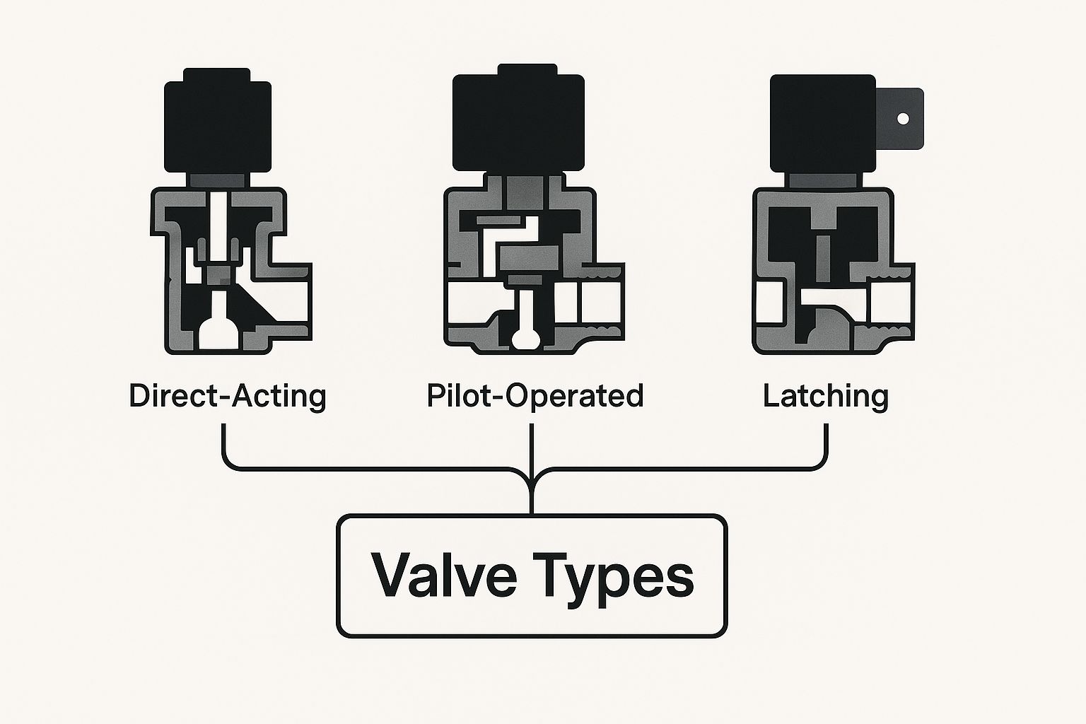
You can see straight away how the internal mechanics of direct-acting, pilot-operated, and latching valves are distinct, each designed for a different kind of control.
Direct-Acting Control: The Brute Force Method
A direct-acting (or direct-operated) solenoid valve is as straightforward as it gets. The control is beautifully simple: when the coil gets power, the magnetic field it creates is solely responsible for pulling the plunger up and opening the valve.
It truly is the brute-force approach. The solenoid coil has to be strong enough to overpower both the fluid pressure and any return spring all by itself. This directness makes them incredibly reliable and fast to respond because their operation doesn't hinge on other factors like the pressure in your system.
Since the coil does all the heavy lifting, these valves are the go-to choice for:
- Low flow-rate applications: The size of the opening is limited by how much force the solenoid can generate.
- Low-pressure systems: Trying to fight high pressure would require a huge, power-hungry coil.
- Vacuum applications: They work perfectly even when there's zero line pressure to help.
Their rugged simplicity makes them a staple in countless industrial automation jobs. In fact, the market for these workhorses is predicted to hit $639.2 million globally by 2025. While that's a worldwide figure, the UK's advanced manufacturing and automation sectors are a big part of that story. You can get more insight into this trend from this detailed industry report.
Pilot-Operated Control: The Smart, Efficient Method
Now, what if you need to manage a much bigger flow or handle seriously high pressure? A direct-acting valve would need a monstrous coil that guzzles energy. This is precisely where pilot-operated (or servo-assisted) valves shine.
Think of a pilot-operated valve like the power steering in your car. A small, easy turn of the steering wheel (the pilot valve) controls a hydraulic system that does the heavy lifting of turning the wheels (opening the main valve).
This type of solenoid valve control uses a clever two-stage trick. The solenoid itself doesn't open the main valve. Instead, it opens a tiny little pilot channel. This small action then cleverly uses the system's own fluid pressure as a force multiplier, making it do the hard work of opening the much larger main valve orifice.
This design is incredibly energy-efficient. The coil only needs enough juice to open the small pilot hole, not fight the entire system pressure. But there's a catch: they need a minimum pressure difference between the inlet and outlet to work properly. Without that differential, there's no force available to lift the main diaphragm or piston.
On/Off Control Versus Proportional Control
Beyond how a valve is physically opened, another vital part of solenoid valve control is what kind of output it gives. Most jobs just need a simple on/off switch, but for more delicate processes, you need something with more finesse.
1. On/Off Control This is the most common setup. The valve is either fully open (maximum flow) or fully closed (zero flow). There's no middle ground. It's the perfect solution for tasks like filling a tank, firing a pneumatic cylinder, or switching on a garden sprinkler.
2. Proportional Control For situations demanding more nuance, a proportional solenoid valve is what you need. Instead of just being on or off, its position can be finely adjusted to any point between fully open and fully closed.
By changing the electrical input (usually a 0-10V or 4-20mA signal), you can precisely dial in the flow rate of the fluid. This is absolutely critical for applications where you have to maintain a specific setpoint, such as:
- Blending hot and cold water to hit a target temperature.
- Regulating the speed of a hydraulic motor.
- Dosing chemicals with high accuracy in a manufacturing process.
Proportional control transforms the solenoid valve from a simple switch into a sophisticated regulation device, unlocking a whole new level of precision for automated systems.
Connecting Electrical Control Signals
A solenoid valve is a powerful bit of kit, but without an electrical signal, it’s just a paperweight. Real solenoid valve control happens where the mechanical and electrical worlds meet. It’s our job to bridge that gap, sending a precise command that sparks the valve into life.
Getting your head around how to power and control your valve is absolutely fundamental. That electrical signal is what kicks the whole process off, creating the magnetic field that moves the plunger. This signal can be as simple as flicking a switch, or it could be a sophisticated command sent from an industrial computer.
At the most basic level, you have to choose the right power source. The two main players are Alternating Current (AC) and Direct Current (DC), and your choice has real-world consequences for how the valve behaves.
Choosing Between AC and DC Power
The voltage you feed into the coil isn't just a number; it directly influences the valve's performance. Neither AC nor DC is inherently "better"—they're just different. Picking the right one comes down to what your specific application needs.
AC (Alternating Current): AC coils give you a strong initial "inrush" of current. This delivers a powerful kick to pull the plunger into position fast, which is great for overcoming high pressures or a bit of stickiness. The trade-off? This inrush can cause a noticeable "click" or hum during operation.
DC (Direct Current): DC coils offer a much smoother, more consistent delivery of power. This means they run silently, without any hum, making them the go-to choice for noise-sensitive places like medical labs or quiet offices. They also generally use less power once they're up and running.
You can think of it like this: an AC coil is like using a hammer on a nail—it’s powerful and quick but makes a racket. A DC coil is more like smoothly pushing the nail in with a press—it’s quiet, controlled, and gets the job done just as well for most tasks.
From Manual Switches to Automated Logic
Once you’ve got the power sorted, the next question is how you’re going to tell the valve when to open or close. The control method can be anything from a simple manual switch right up to a fully autonomous, intelligent system.
A simple toggle switch is the most basic form of solenoid valve control. It lets an operator manually open or close a valve whenever they need to. This is perfect for straightforward jobs, like draining a tank or activating a single pneumatic clamp. This direct approach is common in many setups, and you can learn more about how they are used in our guide to pneumatics solenoid valve systems.
However, modern industry rarely runs on one-off manual actions. For complex, sequential, or responsive operations, you need a "brain" for the system—something that can make decisions automatically. This is where a Programmable Logic Controller (PLC) comes in.
The Role of Programmable Logic Controllers (PLCs)
A PLC is essentially a rugged industrial computer that acts as the central nervous system for an automated process. Instead of a person flipping a switch, the PLC sends the electrical signal to the solenoid valve based on a pre-written program and real-time information from sensors.
Picture a bottling plant. A PLC can orchestrate a whole sequence of events flawlessly:
- A sensor sees that a bottle is in the right position.
- The PLC gets this signal and, after a programmed delay of just 50 milliseconds, sends a 24V DC signal to a solenoid valve.
- The valve opens, filling the bottle with the perfect amount of liquid.
- A flow meter tells the PLC when the correct volume has been dispensed.
- The PLC instantly cuts power to the solenoid, and the valve snaps shut.
This entire dance happens automatically, thousands of times a day, with absolute consistency. The PLC can take inputs from timers, pressure sensors, temperature probes, or any other monitoring device to make intelligent decisions. This connects the simple on/off action of a single valve to the much bigger, dynamic picture of a modern industrial process, turning it from a simple component into a responsive part of a smart system.
Integrating Solenoid Valves into Your System
Choosing the right valve is more than half the battle, but getting it properly integrated into your system is where the real work begins. This is the part where theory meets practice, and getting it right from the start prevents costly failures and ensures your system runs reliably for years.
The first, and arguably most critical, decision you'll make is the valve material. The body of the valve has to be chemically compatible with whatever fluid or gas is flowing through it. A mismatch here is a fast track to problems like corrosion, contamination of your media, and eventually, a total valve failure. It’s a foundational step you simply can’t afford to get wrong.
For example, brass is a fantastic, cost-effective choice for neutral media like air, water, or light oils. But if you’re dealing with aggressive chemicals, food-grade products, or high-purity fluids, you’ll need to step up to stainless steel. Its superior corrosion resistance is non-negotiable for protecting both the valve and the purity of your process.
To make this crucial choice a little easier, here’s a quick guide to common valve materials and where they shine.
Choosing The Right Valve Material
This table serves as a quick reference guide, comparing common valve materials against their ideal applications to help simplify your selection process.
| Material | Best For | Key Advantages | Considerations |
|---|---|---|---|
| Brass | Neutral media (air, water, light oils) | Cost-effective, good machinability | Not suitable for corrosive media like saltwater or strong acids |
| Stainless Steel (304/316) | Corrosive fluids, food & beverage, chemicals | Excellent corrosion resistance, high purity | More expensive than brass, can be overkill for simple jobs |
| Plastic (PVC, PTFE) | Aggressive chemicals, deionised water | High chemical resistance, lightweight | Lower pressure and temperature limits compared to metals |
| Bronze | Seawater, steam, slightly corrosive media | More durable than brass, good corrosion resistance | Can be more costly than brass, specific grades needed for lead-free |
Thinking about the material first sets you up for success with the rest of the installation.
Sizing Your Valve Correctly
Once you’ve picked your material, you need to get the size right. This is absolutely paramount. A valve that’s too small acts like a bottleneck, restricting flow and starving your system, preventing it from ever reaching its performance potential. On the flip side, an oversized valve can cause erratic control, system instability, and a damaging, clattering noise known as "valve chatter."
The key to perfect sizing is the flow coefficient, or Cv value. This isn't just an arbitrary number; it represents the volume of water (in US gallons per minute) that will flow through the valve with a pressure drop of one PSI. To pick the right valve, you need to know your system's required flow rate and the pressure difference (delta-P) across the valve. With those two figures, you can calculate the Cv you need and find a valve that fits your system like a glove.
Think of the Cv value like choosing the right size of pipe for your house. Too small, and your shower pressure is pathetic. Too large, and you've wasted money on plumbing that provides no extra benefit. Correctly matching the Cv ensures your system operates at peak efficiency without compromise.
Matching Pressure and Ports
Just as important are the pressure rating and port connections. Every valve is rated for a maximum operating pressure it can safely handle. Pushing it past this limit is a recipe for disaster, risking serious leaks or even a complete blowout. This is especially true in demanding industries. In fact, the global market for ultra-high pressure (UHP) solenoid valves is projected to reach approximately $3.27 billion by 2025, driven by sectors like the UK's North Sea oil and gas industry where managing extreme pressure is a fundamental safety requirement.
Finally, your valve’s port size and thread type have to match your pipework. A mismatch means you’ll be hunting for adapters, which just add complexity and create extra potential leak points. Planning for this from the start leads to a much cleaner, more robust installation. For practical, hands-on advice, have a look at our guide on solenoid valve installations and maintenance instructions.
When piecing your system together, it’s also good to know about the wide range of available parts, including specialised wellness valve control components that can provide solutions for very specific setups. Taking the time to think through all these integration factors—material, size, pressure, and connections—is the cornerstone of a successful and dependable solenoid valve control system. It’s the practical work that ensures your automated process runs smoothly from day one.
Troubleshooting Common Solenoid Valve Problems

Even the most dependable systems can hit a snag. When a solenoid valve acts up, it can grind an entire process to a halt, which makes a quick and accurate diagnosis absolutely essential. Getting good at troubleshooting is a massive part of reliable solenoid valve control, helping you cut down on downtime and get things running again.
Most of the time, problems come down to a few usual suspects: power, pressure, or something going on inside the valve. If you approach it systematically, starting with the simplest things first, you can often avoid needlessly replacing parts or diving into complicated repairs. This guide will walk you through a logical, field-ready troubleshooting process.
Valve Fails To Open
This is probably the most common headache you'll run into. You give the signal, but nothing happens—the flow stays blocked. Before you jump to the conclusion that the valve itself is shot, it's worth checking a few other things first.
- No Electrical Power: It might sound blindingly obvious, but this is always your first port of call. Use a multimeter to confirm the power is on and the coil is actually receiving the correct voltage.
- Burnt-Out Coil: If the power is there but the valve isn't responding, the coil might have given up the ghost. A burnt coil often has a telling smell or visible scorch marks. An open circuit reading on your multimeter will confirm it's dead.
- Incorrect Voltage: Trying to power a 24V DC valve with 12V DC, for instance, just won't generate enough magnetic oomph to lift the plunger. Always double-check that your supply voltage matches what’s stamped on the coil's specification plate.
- Pressure Issues (Pilot-Operated): Remember, pilot-operated valves need a minimum pressure difference to work their magic. If the system pressure is too low or there isn't enough of a pressure drop across the valve, it simply won't have the force to open the main orifice.
A methodical approach to troubleshooting is your most valuable tool. Rushing to replace a valve without first checking the power supply or system pressure can waste time and money on a problem that was simple to fix.
Valve Fails To Close
Just as frustrating is a valve that refuses to shut, causing a continuous and unwanted flow. This issue often points to a mechanical blockage or a component that’s become stuck in the open position.
A very common culprit is a bit of debris that's gotten lodged inside the valve body. This physically prevents the plunger or diaphragm from seating properly and creating a tight seal. You see this a lot in systems that don't have good filtration. Another possibility is a damaged or worn-out seal or diaphragm that can no longer do its job.
For a more detailed breakdown of diagnostics, our complete engineering guide offers deeper insights. You can find more in our post on https://www.solenoid-valve.world/solenoid-valve-mastery-your-complete-engineering-guide.
Other Common Issues And Fixes
Beyond the simple open-and-shut cases, other symptoms can point to trouble. If an AC valve is making a loud buzzing or chattering sound, it's often a sign of low voltage or debris stopping the plunger from seating fully. With pilot-operated valves, a weak or slow response can be a clue that the tiny pilot channel is blocked and needs a good clean-out.
While we're focused on solenoid valves here, many of these diagnostic principles apply across all sorts of systems. For some broader tips that might come in handy, checking out an HVAC troubleshooting guide can offer some valuable, transferable knowledge.
Frequently Asked Questions about Solenoid Valves
Even when you've got a handle on the basics, there are always a few specific questions that pop up on the job. Let's tackle some of the most common queries we hear, giving you quick, practical answers to keep your solenoid valve control systems running smoothly.
What Is the Difference Between a 2-Way and a 3-Way Solenoid Valve?
Think of a 2-way valve as a simple on/off switch for liquids or gases. It has two ports—one in, one out. Its entire job is to either let the fluid pass or stop it completely. It’s either fully open or fully closed, which makes it the go-to choice for straightforward tasks like filling a tank or draining a system.
A 3-way valve, on the other hand, is more like a set of points on a railway track. With its three ports, it’s designed to divert flow from one path to another. You can use it to switch the output between two different destinations or to control a single-acting cylinder by first applying pressure and then venting it.
Can I Use an AC Coil with DC Power?
In a word: no. This is one of the golden rules you can't afford to break. You must always match the power supply to the exact voltage and current type specified for the coil.
If you connect DC power to an AC coil, it will overheat and burn out in no time. The coil relies on the natural resistance (impedance) of an AC circuit to limit the current, and a DC supply simply lets too much power rush in.
Conversely, hooking up an AC supply to a DC coil won't work either. You’ll get a loud buzzing or chattering sound as the magnetic field fluctuates rapidly, making the plunger vibrate instead of seating firmly. This will quickly lead to the valve failing.
Always double-check the voltage and current type (AC/DC) printed directly on the coil before you connect any power. A power mismatch is one of the most common—and most easily avoided—reasons for valve failure.
How Important Is the Mounting Position?
The mounting position can be absolutely critical for the valve to work reliably. Most solenoid valves are engineered to be mounted with the coil positioned vertically, right on top of the valve body. This allows gravity to give the plunger a helping hand on its return journey when you de-energise the coil.
If you mount the valve on its side, or even worse, upside down, you're working against physics. The plunger might struggle to overcome friction without gravity's assistance, which can lead to it sticking open, sticking closed, or just operating unreliably. Always check the manufacturer's installation guide for the recommended orientation.
For all your fluid control needs, from standard brass valves to highly specialised ATEX-certified solutions, Solenoid Valve World has you covered. Explore our extensive range and find the perfect component for your system today at https://solenoid-valve.world.