How to Size a Valve The Right Way
When it comes to valve selection, getting the size right isn't just a box-ticking exercise. It's about finding the sweet spot where your valve works efficiently and reliably for years to come. The process boils down to calculating the required flow coefficient (Cv) from your system's data—like flow rate, pressure drop, and the fluid you're working with—and then picking a valve that matches that Cv.
The aim is to find a valve that, under normal conditions, operates somewhere between 50% and 80% open. This range gives you the best control and helps maximise the valve's working life.
Why Getting Valve Sizing Right Is Crucial
Let's be blunt: getting valve sizing wrong can have some seriously expensive and dangerous consequences. We're moving beyond textbook theory here. In the real world, a poorly sized valve can destabilise your entire operation and, in a worst-case scenario, lead to catastrophic equipment failure.
The Problem with Oversized Valves
It might seem like a bigger valve is a safer bet, but the opposite is true. When a valve is too large for the job, it has to operate almost completely shut just to manage the flow. This tiny operating window leads to a problem called "chattering," where the valve plug constantly judders against its seat.
This creates a cascade of issues:
- Poor Control: The slightest adjustment can cause a massive, unpredictable change in flow, making stable control impossible.
- Premature Wear: The constant chattering rapidly erodes the plug and seat, drastically shortening the valve's lifespan.
- System Instability: The whole process becomes difficult to manage, which can impact product quality and consistency.
- Skyrocketing Maintenance Costs: You'll be repairing and replacing the valve far more often than you should.
The Dangers of Undersized Valves
On the flip side, a valve that's too small acts like a bottleneck in your pipeline. To force the required amount of fluid through, your system has to work overtime, causing a huge pressure drop across the valve. All that wasted energy doesn't just disappear—it turns into noise, vibration, and heat.
One of the most destructive effects of an undersized valve is cavitation. If the pressure drops low enough, the liquid can actually boil, forming vapour bubbles. As the pressure recovers downstream, these bubbles violently collapse. The force is immense, strong enough to pit and chew through even the toughest valve materials, leading to swift and total failure.
In the UK, we rely on established standards to help avoid these exact problems. Below is a list of common valve sizing standards from Tameson, which provide a clear framework for making the right choice.
Following these standards is about more than just compliance; it's about ensuring your components are genuinely fit for purpose.
Real-World Impact: Imagine a critical cooling loop in a manufacturing plant. An undersized valve restricts coolant, causing equipment to overheat. An oversized one makes temperature control a nightmare. Either mistake could shut down the entire production line, costing thousands of pounds an hour.
Here in the UK, standards like BS 5150 are vital. This particular standard outlines everything for cast iron gate valves, from physical dimensions to pressure testing. Adhering to these guidelines is your best defence against the failures we've talked about. You can learn more about the various UK valve size standards on tameson.co.uk.
Ultimately, knowing how to size a valve correctly is a fundamental skill. It’s what protects your equipment, keeps your people safe, and ensures your operation remains profitable.
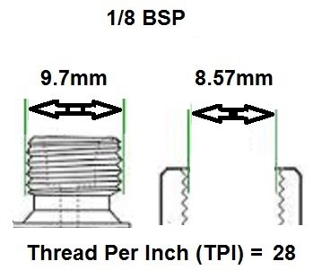
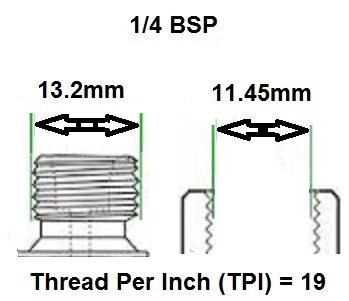
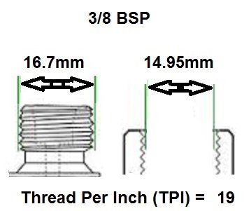
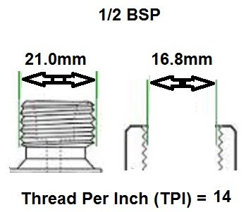
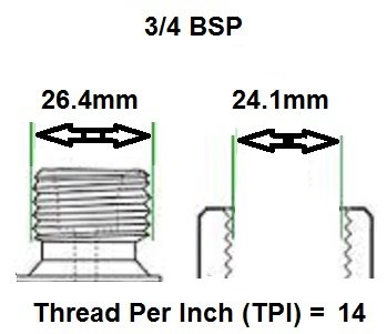
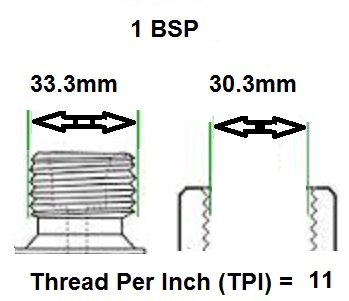
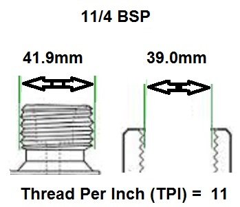
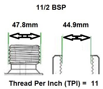
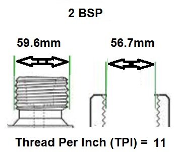
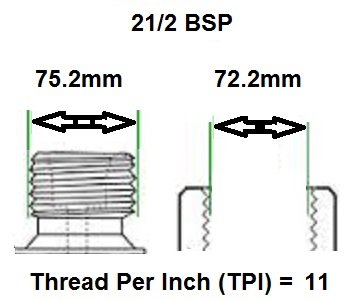
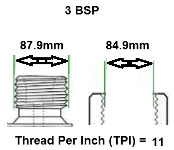
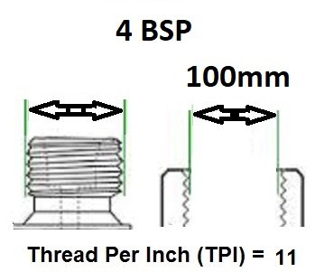
Dimensional thread guide for BSP threads.
Click any thread image to view solenoid valves by thread size
View all Sub Base / Manifold mounted valves
View all Valves with Hose barb/ tail ends
View all NAMUR Mount Valves
View all valves with 90 degree / right angle inlet to outlet
View all valves with push git or compression ends.
View all valves with Solder Welded ends.
Search all valves online by size.
Nailing Down Your Essential Process Data
Before you can even think about calculations, you have to get your hands on some solid process data. It's the absolute foundation for sizing a valve correctly. I always think of it like a pre-flight checklist – if you miss a single detail, you're setting yourself up for a valve that either underperforms or, even worse, fails completely. The old saying 'garbage in, garbage out' has never been truer than it is here.
First things first, you need to know the fluid type. Are we dealing with a liquid, a gas, or steam? Each one behaves entirely differently under varying pressures and temperatures, which means they all need their own specific calculation methods.
With the fluid identified, the next critical piece of the puzzle is the required flow rate (Q). This is simply how much fluid needs to move through that valve over a set period to keep your process happy. You'll typically see this measured in gallons per minute (GPM), cubic metres per hour (m³/h), or sometimes kilograms per hour (kg/h).
Finding Your Pressure and Temperature Figures
Now, let's talk pressure. You’ll need to track down the upstream and downstream pressures, which are almost always labelled P1 and P2. P1 is the pressure of the fluid just as it enters the valve, and P2 is the pressure as it leaves. The difference between them (ΔP, or pressure drop) is what actually pushes the fluid through the valve.
You also can't forget the fluid temperature at the inlet. Temperature has a direct impact on a fluid's properties, particularly its density and viscosity, both of which are crucial for getting your calculations right. For gases and steam, temperature isn't just a nice-to-have; it's an essential part of the sizing formula.
So, where do you find all this? Your best bets are usually:
- Piping and Instrumentation Diagrams (P&IDs): These are the blueprints for your system and should lay out the operating pressures and temperatures.
- Process Datasheets: These documents list out the specific design conditions for a piece of equipment or even a whole system.
- Control System Setpoints: Your facility's control system will have target values for pressure and temperature that can give you the data you need.
Getting to Grips with Fluid Properties
For liquids, you're going to need the specific gravity (SG). That's just the ratio of your liquid's density compared to the density of water. If you're working with gases, you'll need the molecular weight or the specific gas constant instead. These values are non-negotiable for accurately converting volumetric flow to mass flow and accounting for compressibility.
But what if you're dealing with a less common substance? Don't even think about guessing. You can find reliable fluid property tables in engineering handbooks, scientific databases, or often right on the chemical manufacturer's safety data sheets (SDS). Getting this spot-on now will save you from major headaches later.
A mistake I’ve seen time and again is engineers just assuming a pressure drop instead of properly calculating it from P1 and P2. If you only have one pressure value, you have to find the other one. Trusting an estimate for pressure drop is a surefire way to end up with the wrong valve.
How to Handle Tricky Situations
Of course, the data isn't always served up on a silver platter. What if the pressure drop isn't explicitly stated? It’s on you to find both the upstream and downstream pressures and calculate it yourself. Never fall into the trap of assuming a "typical" pressure drop, as this can change drastically from one system to the next.
For example, in a system fed by a pump, P1 is linked to the pump's discharge pressure, minus any friction losses in the pipework leading up to the valve. P2 is the pressure the downstream process needs, plus any head loss in the piping after the valve.
Doing this groundwork properly is what separates a smooth, successful installation from a problematic one. It’s the hard work upfront that makes everything else fall into place.
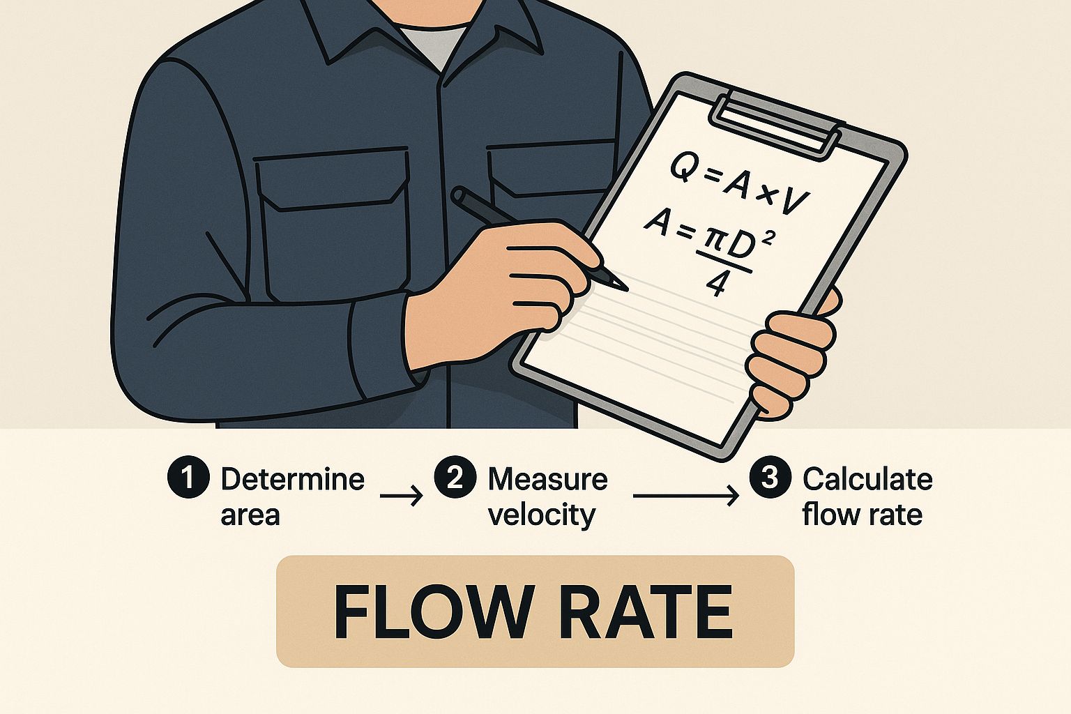
Right, you've gathered all your essential process data. Now we get to the heart of the matter: sizing a valve correctly. The entire process hinges on a single, crucial figure—the Flow Coefficient, better known as Cv.
Think of Cv as the universal passport for a valve. It’s a standard measure of its capacity, telling you precisely how much fluid can get through it at a specific pressure drop.
Nailing this Cv calculation for your particular setup is the most critical step. It’s not just important; it's a non-negotiable prerequisite before you even think about looking at a manufacturer's catalogue. Get this number wrong, and you're building on a faulty foundation. The good news is that the maths is quite straightforward once you know which formula to use for liquids, gases, or steam.
This is where your initial data collection pays off. Before you can even touch a formula, you need a solid handle on your required flow rate, as it's the main variable driving the whole calculation.
Sizing for Liquids
For most liquid applications, the calculation is refreshingly simple. The standard formula is an old industry friend, a reliable workhorse that has connected flow rate, pressure drop, and fluid properties for decades.
You’ll be using this classic formula:
Cv = Q * √(SG / ΔP)
Let's quickly unpack what each of those variables means in the real world:
- Q is your flow rate. For this formula, it needs to be in US Gallons per Minute (GPM).
- SG is the specific gravity of the liquid. It’s just a ratio of your liquid’s density compared to water, which has an SG of 1.0.
- ΔP is the pressure drop across the valve in pounds per square inch (psi). This is simply the difference between the pressure going in (P1) and the pressure coming out (P2).
A Word of Warning: Always, always double-check your units. This formula is built for GPM and PSI. If your data is in metric units like m³/h and bar, you absolutely must convert them first. It’s a simple oversight that can lead to choosing a completely wrong valve size. I've seen it happen.
Let’s walk through a quick, practical example. Imagine you’re controlling a light oil with a specific gravity of 0.9. Your target flow rate (Q) is 150 GPM, and you've determined the allowable pressure drop (ΔP) is 10 psi.
Plugging those numbers into our formula, we get:
Cv = 150 * √(0.9 / 10)Cv = 150 * √(0.09)Cv = 150 * 0.3Cv = 45
For this job, you need to find a valve with a required Cv of 45. This is the number you’ll take to the datasheets to start comparing models. If you want to dive deeper into how this coefficient works, our comprehensive guide on the valve flow coefficient is a great resource.
Core Cv Formulas for Different Fluid Types
To make things easier, here’s a quick-reference table with the fundamental formulas for calculating the required Flow Coefficient (Cv) for the most common fluid types.
| Fluid Type | Governing Formula | Key Variables Explained |
|---|---|---|
| Liquid | Cv = Q * √(SG / ΔP) |
Q = Flow Rate (US GPM) SG = Specific Gravity (Water = 1) ΔP = Pressure Drop (psi) |
| Gas | Cv = Q / (1360 * √((ΔP * P2) / (SG * T))) |
Q = Flow Rate (SCFH) P2 = Outlet Pressure (psia) T = Absolute Temp (°F + 460) SG = Specific Gravity (Air = 1) ΔP = Pressure Drop (psi) |
| Steam | Varies (Saturated/Superheated) | Calculations for steam are more complex and often use specific formulas or tables from engineering handbooks or manufacturer software. The state of the steam (saturated vs. superheated) is critical. |
These formulas are the starting point for any manual calculation. Having a feel for them is crucial, even if you end up using sizing software.
Sizing for Gases and Steam
When we move on to gases and steam, things get a bit more complicated. Unlike liquids, which are pretty much incompressible, the density of a gas or steam changes significantly with pressure and temperature. This means our calculations need to factor in compressibility.
There's another critical phenomenon we have to account for: choked flow.
Also known as critical flow, this happens when the gas velocity at the valve's narrowest point (the vena contracta) hits the speed of sound. Once you hit that point, dropping the downstream pressure any further won't increase the flow rate. The valve is effectively giving you everything it's got. Your calculations must anticipate this possibility.
Because of these added layers of complexity, many experienced engineers lean on specialised software or the online calculators provided by valve manufacturers. These tools have the tricky formulas for choked flow and different gas properties baked right in, which seriously cuts down the risk of calculation errors.
Even so, understanding the principles behind the numbers is vital. It allows you to sense-check the results and make a truly informed decision. Knowing what goes into the calculation helps you spot when an input looks off or when a result just doesn't feel right.
Matching Your Cv to a Real-World Valve
You've done the hard maths and have your required Cv value. That's the theory sorted. Now for the practical part: turning that number into an actual piece of hardware you can install. It's time to dive into manufacturer datasheets to find the perfect valve for your system.
A calculated Cv on its own is just a number on a page. Its real power lies in how it guides you through a sea of valve options to find the one that fits your system's needs perfectly. This isn't just about matching numbers; it’s about knowing how a valve will behave in your specific application.
Interpreting Manufacturer Datasheets
When you crack open a manufacturer's datasheet, you'll find plenty of tables and charts. Your main focus should be the Cv tables. These list the maximum flow coefficient for each valve size within a specific model range. The trick is to find a valve where its maximum Cv is comfortably above your calculated requirement.
Let's say you calculated a required Cv of 45. You might be tempted to grab a valve with a maximum Cv of exactly 45, but that would be a mistake. It means the valve would have to be 100% open just to handle your normal flow, leaving absolutely no room for control or to handle any future process tweaks.
Understanding valve sizing means appreciating the sheer scale of industrial needs. The UK control valve market was estimated at USD 292 million in 2023, a figure that shows just how many different applications there are, with valve sizes ranging from less than an inch to over 50 inches. This diversity is exactly why precise sizing is so critical for boosting efficiency and cutting energy use across the board. You can see more on these trends in the UK control valve market report on marketresearchfuture.com.
The image below gives you a sense of this breakdown by size, highlighting just how much demand there is across the industrial spectrum.
As you can see, while smaller valves (1" to 6") are extremely common, there's significant use of much larger sizes. It just reinforces why getting the sizing right is non-negotiable, no matter the scale.
The Sweet Spot for Valve Operation
Experienced engineers live by a simple but crucial rule of thumb. Following this guideline will save you from a world of operational headaches and ensure your system runs smoothly for years to come.
The Golden Rule: Choose a valve where your normal operating flow rate requires it to be between 50% and 80% open.
So, why is this specific range so important?
- Below 50% Open: Operating a valve this close to its seat gives you terrible control. Tiny movements of the actuator can cause massive, jerky changes in flow, making a stable process almost impossible to achieve.
- Above 80% Open: When a valve is almost fully open, you have very little headroom. If you ever need to increase the flow, you've got nowhere to go. It also puts a lot more stress on the internal parts, leading to faster wear and tear.
Sticking to this 50-80% range is the key to a responsive, stable, and durable control valve installation.
A Practical Selection Example
Let's bring this all together. Remember our earlier calculation, where we landed on a required Cv of 50 for our normal flow rate. We’re now looking at a manufacturer’s datasheet for a globe valve.
These are our options:
| Valve Size | Maximum Cv (100% Open) |
|---|---|
| 2-inch | 48 |
| 3-inch | 85 |
| 4-inch | 150 |
Let’s walk through the choices:
- The 2-inch valve is out immediately. Its maximum Cv is 48, which is less than our required 50. It's physically incapable of handling the flow.
- The 4-inch valve is way too big. To get our Cv of 50, it would only be about 33% open (
50 / 150). This is well below our 50% minimum and would almost certainly lead to poor control and chattering. - The 3-inch valve looks like our winner. To achieve the required Cv of 50, it would be sitting at roughly 59% open (
50 / 85). This is right in the middle of our ideal 50-80% operating range.
The 3-inch valve is the clear choice. It gives us the flow we need while operating in that sweet spot for excellent control and a long, reliable service life. This is also the point where you’d think about what kind of actuator you need. Our guide to pneumatic actuators for valves can walk you through the options for getting your chosen valve automated.
Getting Beyond the Basics: Advanced Sizing Factors
Nailing the flow coefficient (Cv) is a huge first step, but it’s not the end of the story. Any seasoned engineer will tell you that a few other critical factors can make or break your valve selection. Ignoring these details is a classic rookie mistake, and it often leads to noisy operation, damaged components, or even a total system shutdown. This is where experience comes in, turning a decent valve choice into a truly robust and reliable one.
Once you’ve moved past the basic Cv formula, you need to look at the destructive forces that can wreak havoc inside a valve, especially when you’re dealing with liquids.
This chart gives you a great visual of what happens to pressure as a fluid passes through a valve. See that big dip at the vena contracta? That’s precisely where dangerous phenomena like flashing and cavitation are born, and it’s why a deeper analysis is so important.
Predicting Cavitation and Flashing
As a liquid shoots through the narrowest part of the valve (what we call the vena contracta), its speed rockets up and its pressure plummets. If that pressure drops below the liquid’s vapour pressure, it starts to boil, forming tiny vapour bubbles. What happens to those bubbles next is the key difference between flashing and cavitation.
- Flashing: If the pressure downstream (P2) stays below the vapour pressure, the bubbles remain as vapour. You end up with a two-phase flow of liquid and gas, which is incredibly erosive and loud.
- Cavitation: This is often worse. If the downstream pressure recovers and climbs back above the vapour pressure, those bubbles violently collapse—they implode. The force from this implosion is immense, creating powerful shockwaves that can pit, erode, and chew through even hardened valve internals.
To sidestep this nightmare, you have to compare the pressure at the vena contracta with your fluid's vapour pressure. Manufacturers provide crucial data, like a valve’s Liquid Pressure Recovery Factor (FL), to help you predict if cavitation is a risk. If your numbers show a problem, you’ll need a valve with special anti-cavitation trim designed to handle these conditions.
Dealing With High-Viscosity Fluids
Standard Cv calculations are built on the assumption that you’re working with a free-flowing fluid like water. But if you’re moving viscous fluids—think heavy oils, syrups, or sludge—you’ve got to make some adjustments. High viscosity means more internal friction, which chokes off a valve's effective flow capacity. A valve with a Cv of 100 for water might only manage an effective Cv of 70 for a thick oil.
For these applications, you need to apply a Viscosity Correction Factor (Fv) to your initial Cv calculation. You’ll find charts and formulas for this in manufacturer handbooks and sizing software, which use the fluid’s viscosity (in centistokes), valve size, and the Reynolds number to find the right factor. Skip this, and you’ll almost certainly undersize your valve.
Expert Tip: When sizing for viscous liquids, always err on the side of caution. If you're on the borderline between two valve sizes after applying the correction factor, going for the slightly larger one is usually the safer move. This ensures you meet your flow rate without an excessive pressure drop.
Predicting and Tackling Noise
Valve noise isn't just an irritation; it’s a red flag. It points to wasted energy and can be a symptom of destructive forces at play, whether aerodynamic or hydrodynamic. Noise levels over 85 dBA can breach site safety rules and often signal severe turbulence, vibration, or cavitation. In gas systems, it’s usually high-pressure drops that are the noisy culprits.
Predicting noise levels is a complex business, laid out in standards like IEC 60534-8-3 and 60534-8-4. Luckily, most modern valve sizing software handles these calculations for you. If the prediction looks loud, the solution is to pick a valve with low-noise trim. These specially designed cages or plugs break one large pressure drop into several smaller, much quieter ones.
For potable water systems in the UK, making sure your setup complies with water regulations is also paramount. This is why sourcing certified parts like WRAS-approved valves is non-negotiable.
Ultimately, safety and pressure regulation are at the heart of valve sizing in UK industry. This is all underpinned by the Pressure Equipment (Safety) Regulations 2016, which apply to systems operating above 50 kPa. Furthermore, standards like BS EN ISO 4126:2019 dictate specific sizing rules for safety valves, ensuring they function as intended when it matters most.
Common Valve Sizing Questions Answered
Even with the best formulas and a solid process, a few nagging questions always seem to pop up when you're sizing a valve. The gap between theory and what actually happens in a real-world system can be tricky to navigate. Let's tackle some of the most common questions we hear from engineers and technicians to clear up any confusion and help you choose the right valve with confidence.
Getting these details right is about more than just accuracy; it’s about preventing the common pitfalls that lead to poor system performance and equipment that wears out far too soon.
What Happens If I Choose an Oversized Valve?
This is a classic concern, and for very good reason. When a valve is too big for the job, it has to operate almost completely shut just to manage the normal flow rate. This creates a whole host of problems.
For one, the valve becomes incredibly sensitive. The tiniest adjustment can cause a massive change in flow, making any kind of precise control feel impossible. This often leads to "chattering," a rapid juddering of the valve plug against its seat. This constant hammering causes significant wear and tear on the valve’s internals, particularly the seat and stem packing, which drives up maintenance costs and dramatically increases the risk of an unexpected failure.
How Do I Size a Valve for a Fluid That Isn't Water?
When you’re working with anything other than water, you absolutely have to factor in its unique properties. For other liquids, this means using the fluid’s specific gravity (SG) in your calculation. The standard formula Cv = Q * √(SG / ΔP) is specifically designed for this.
Gases are a bit more involved because their density is very sensitive to changes in pressure and temperature. For these, you'll need to use more complex formulas that account for the gas's molecular weight, temperature, and compressibility. Always dig out the correct formula and fluid data for your specific substance to get a reliable result.
Key Takeaway: Never, ever assume water properties for other fluids. Even a small difference in specific gravity or density can throw your Cv calculation off completely, leading you straight to the wrong valve. It's one of the most frequent mistakes people make when learning how to size a valve.
What Is Choked Flow and How Does It Affect Sizing?
Choked flow is a critical concept you’ll encounter in gas and steam systems. It’s what happens when the fluid’s velocity hits the speed of sound as it passes through the valve's narrowest point (the vena contracta).
Once this occurs, a fascinating physical limit is reached. It doesn’t matter how much more you increase the pressure drop across the valve; you simply cannot push any more mass through it. The valve is effectively maxed out. Any sizing calculation for a compressible fluid has to include a check for choked flow conditions. If your system is going to operate in a choked state, you must ensure the valve can still pass the required mass of fluid under those limiting conditions.
Should I Choose a Linear or Equal Percentage Characteristic?
This choice really boils down to how your specific system behaves. A valve's flow characteristic simply describes the relationship between how far the valve is open and the flow rate you get as a result.
- Linear: Go for a linear characteristic valve when the pressure drop across it stays relatively constant, even as the flow rate changes. This is quite common in applications like liquid level control.
- Equal Percentage: Opt for an equal percentage characteristic if you anticipate large swings in pressure drop. This is typical for most pressure and temperature control loops. This type gives you much finer, more proportional control at lower flow rates and handles dynamic system changes much more gracefully.
At Solenoid Valve World, we know that getting the right valve is crucial for your system's performance and safety. Our extensive online catalogue and UK-based technical support team are here to help you match your calculated requirements to the perfect product. Explore our comprehensive selection of valves and control equipment at https://solenoid-valve.world.