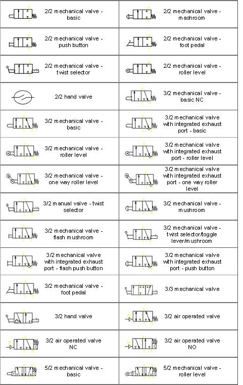
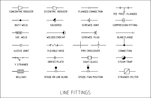
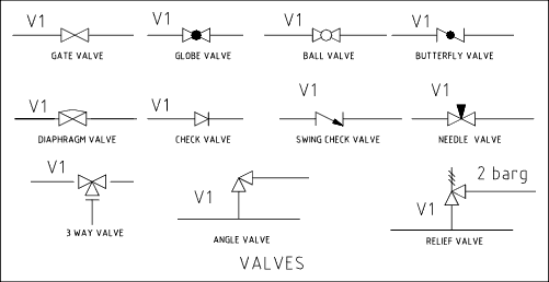
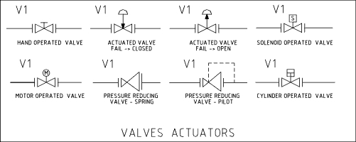
Common Solenoid Valve and other Pneumatic symbols.
A detailed view of pneumatic circuit symbols and their meaning. Valve symbols including solenoid valve symbols are those that are in common use. Solenoid Valve Symbols:
|
|
|
|
|
 Accumulator Accumulator |
|
 Air Motor - flow one direction Air Motor - flow one direction |
 Air motor - flow two directions Air motor - flow two directions |
|
 Compressor Compressor |
 Cylinder - Spring return Cylinder - Spring return |
 Cylinder - Double Acting with double rod Cylinder - Double Acting with double rod |
 Cylinder - Double acting with single fixed cushion Cylinder - Double acting with single fixed cushion |
 Cylinder - Double acting with two adjustable cushions Cylinder - Double acting with two adjustable cushions |
 Differential pressure Differential pressure |
 Direction of flow Direction of flow |
 Exhaust Line - control line Exhaust Line - control line |
|
|
|
 Fixed restriction Fixed restriction |
 Flexible hose line Flexible hose line |
|
 Flow Gauge Flow Gauge |
|
 Line Connected Line Connected |
 Lines crossing Lines crossing |
|
|
 One bypass flow valve and two closed ports One bypass flow valve and two closed ports |
 One flow path One flow path |
|
|
|
 Plugged Port Plugged Port |
 Plunger or Position Indicator Plunger or Position Indicator |
 Pneumatic Pneumatic |
 Pressure Actuated Switch Pressure Actuated Switch |
|
|
|
|
|
|
|
|
|
|
|
 Spring Spring |
|
 Two distinct positions and one transitory position Two distinct positions and one transitory position |
 Two flow paths Two flow paths |
 Two flow paths with cross connection Two flow paths with cross connection |
 Vacuum Pump Vacuum Pump |
 Variable Restriction Variable Restriction |
|


 Quick Connect Coupling
 Roller


 Solenoid with pilot and manual over ride


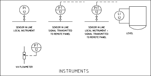
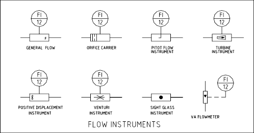
Instrument Identifiers
| Measured Variable |
Type of Conditioner |
Type of Component |
| F = Flow |
R = Recorder |
T = Transmitter |
| L = Level |
I = Indicator |
M = Modifier |
| P = Pressure |
C = Controller |
E = Element |
| Q = Quantity |
A = Alarm |
|
| T = Temperature |
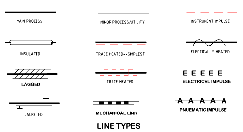
Connexion Solenoid Valve symbols from the UK's premier solenoid valve suppliers Symbols for Process Equipment |
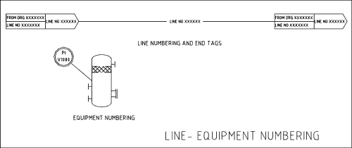
The levels of detail for process equipment relates to the schematic type produced. A process flow sheet will only show basic levels of technical information sufficient to highlight essential process flow paths. An engineering line diagram of P and ID will show a lot more detailed comprehensive information and technical detail.
Equipment Process Plant -1
Equipment Process Plant - 2
Line tags and equipment identification.
Reading Pneumatic Schematic Symbols
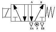 
5/2 Valve has 5 ports and 2 possible conditions
1.) B is pressurized and A is exhausted.
2.) A is pressurized and B is exhausted.
When the solenoid is NOT energised the B port is pressurized. The spring symbol defines the valve position at rest.
The Block