DIN 43650 Electrical Connectors for Solenoid Valves
Comprehensive guide overview of DIN 43650 connectors
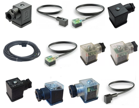
DIN 43650 connectors, also known as EN 175301-803 connectors, are standardised electrical connectors commonly used to connect solenoid valves to power sources. They are designed to provide a secure and water-resistant connection in various industrial applications, including hydraulics, pneumatics, and marine environments.
Types of DIN 43650 Connectors
There are three primary forms of DIN 43650 connectors, each differing in size, pin configuration, and application suitability:
Form A DIN Connectors → View Products
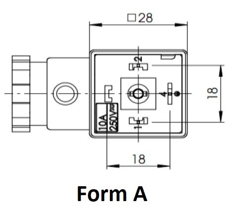
Pin Spacing: 18 mm
Pin Configuration: 2 or 3 pins plus ground
Housing Shape: Square (28 mm x 28 mm)
Applications: Ideal for general-purpose solenoid valves in hydraulics and pneumatics
Features: Available with or without circuitry, including options for LED indicators, surge suppression (VDR), and bridge rectifiers
Protection Rating: Up to IP67, depending on the model
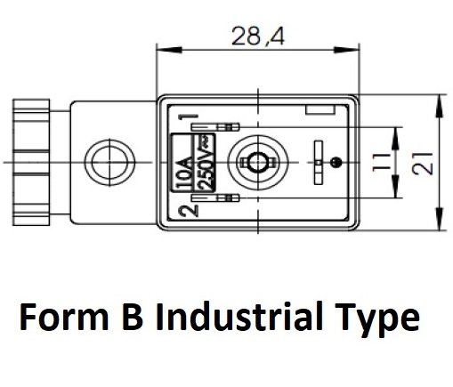
Form B Industrial Connectors (11mm) → View Products
Form B DIN Connectors (10mm) → View Products
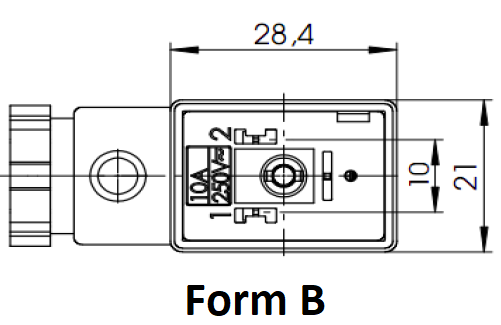
Pin Spacing: 10 mm analogue or 11 mm Industrial
Pin Configuration: 2 pins plus ground
Housing Shape: Rectangular
Applications: Suitable for space-constrained installations, such as manifold banks
Features: Options include LED indicators and surge protection
Protection Rating: Up to IP67
Form C DIN Connectors (9.4mm Micro) → View Products
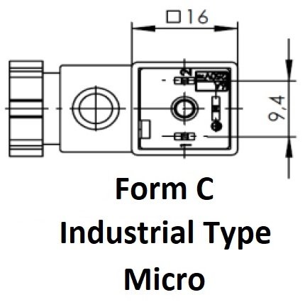
Form C DIN Connectors (8mm Analogue) → View Products
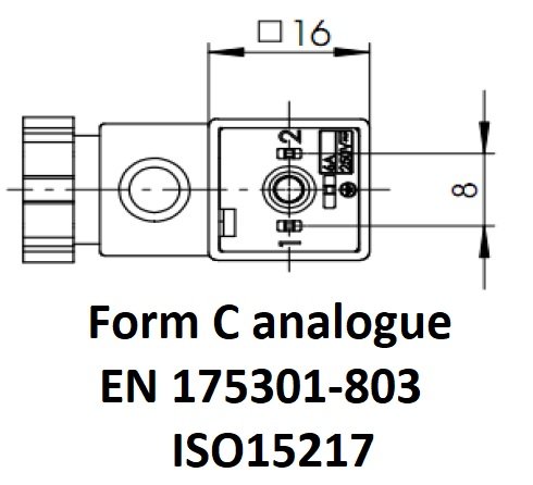
Pin Spacing: 8 mm analogue or 9.4 mm Micro
Pin Configuration: 2 or 3 pins plus ground
Housing Shape: Square (smaller than Form A)
Applications: Used in compact devices like pressure sensors and proximity switches
Features: Available with LED indicators and surge protection
Protection Rating: Up to IP67
Wiring and Installation Guidelines
Proper wiring and installation are crucial for the reliable operation of DIN 43650 connectors:
Polarity: Connect the positive power supply (typically red or brown wire) to terminal 1, and the negative return (black or blue wire) to terminal 2.
Cable Entry: Ensure the cable entry faces downward to prevent water ingress.
Strain Relief: Use the appropriate cable diameter for the connector's PG rating to achieve a tight seal.
Torque Settings: Adhere to recommended torque settings to maintain IP protection:
Strain relief nut: 1.8 N·m ±10%
Central fixing screw: 0.4 N·m ±10%
Contact screws: 0.2 N·m ±10%
DIN 43650 Connectors → View Full Range
Why Choose Solenoid Valve World?
Extensive Inventory: Wide range of connectors in stock, ensuring quick delivery.
Quality Assurance: Products adhere to international standards, providing reliable performance.
Competitive Pricing: Affordable solutions without compromising on quality.
Expert Support: Knowledgeable staff available to assist with product selection and technical queries.
Form A DIN Connectors → Shop Online
Form B Industrial Connectors (11mm) → Shop Online
Form C DIN Connectors (9.4mm Micro) → Shop Online
TVS vs VDR (MOV) — what’s the real difference?
🔹 TVS (Transient Voltage Suppressor diode)
Very fast response (nanoseconds)
Tight clamping voltage (more precise protection)
Designed for low-voltage electronics (like your 24V coil circuit)
Handles short, sharp spikes very well
Typically lower energy capacity than MOVs
🔹 VDR / MOV (Varistor)
Slower response (microseconds range)
Softer clamping (lets voltage rise higher before limiting)
Handles higher energy surges (e.g. mains spikes, lightning transients)
Degrades over time with repeated hits
More common in 230V/120V mains protection
In your connector (important context)
You’re dealing with:
24V AC/DC
Inductive load (solenoid coil)
Built-in LED + protection
👉 That means the spike is:
Frequent but relatively low energy
Generated by coil switching (inductive kickback)
So why TVS here?
Because:
It reacts fast enough to clamp the coil flyback spike cleanly
Keeps voltage within a safe, controlled level (~37.8V in your spec)
Doesn’t degrade like a MOV in repetitive switching
Is TVS “better” than VDR?
For this application → YES
In general → NO, just application-specific
| Use case | Better choice |
|---|---|
| 24V solenoid / control circuits | ✅ TVS |
| Mains surge protection (230V) | ✅ MOV (VDR) |
| Precision electronics protection | ✅ TVS |
| High-energy surge (lightning, grid) | ✅ MOV |
Practical takeaway
That connector uses a TVS because it’s protecting electronics from switching transients, not absorbing big power surges.
If you swapped it for a MOV:
It would still “work”
But protection would be slower, less precise, and less repeatable